|
|
|
PDF SiB412DK Data sheet ( Hoja de datos )
| Número de pieza | SiB412DK | |
| Descripción | N-Channel 20-V (D-S) MOSFET | |
| Fabricantes | Vishay | |
| Logotipo | ||
Hay una vista previa y un enlace de descarga de SiB412DK (archivo pdf) en la parte inferior de esta página. Total 7 Páginas | ||
|
No Preview Available !
New Product
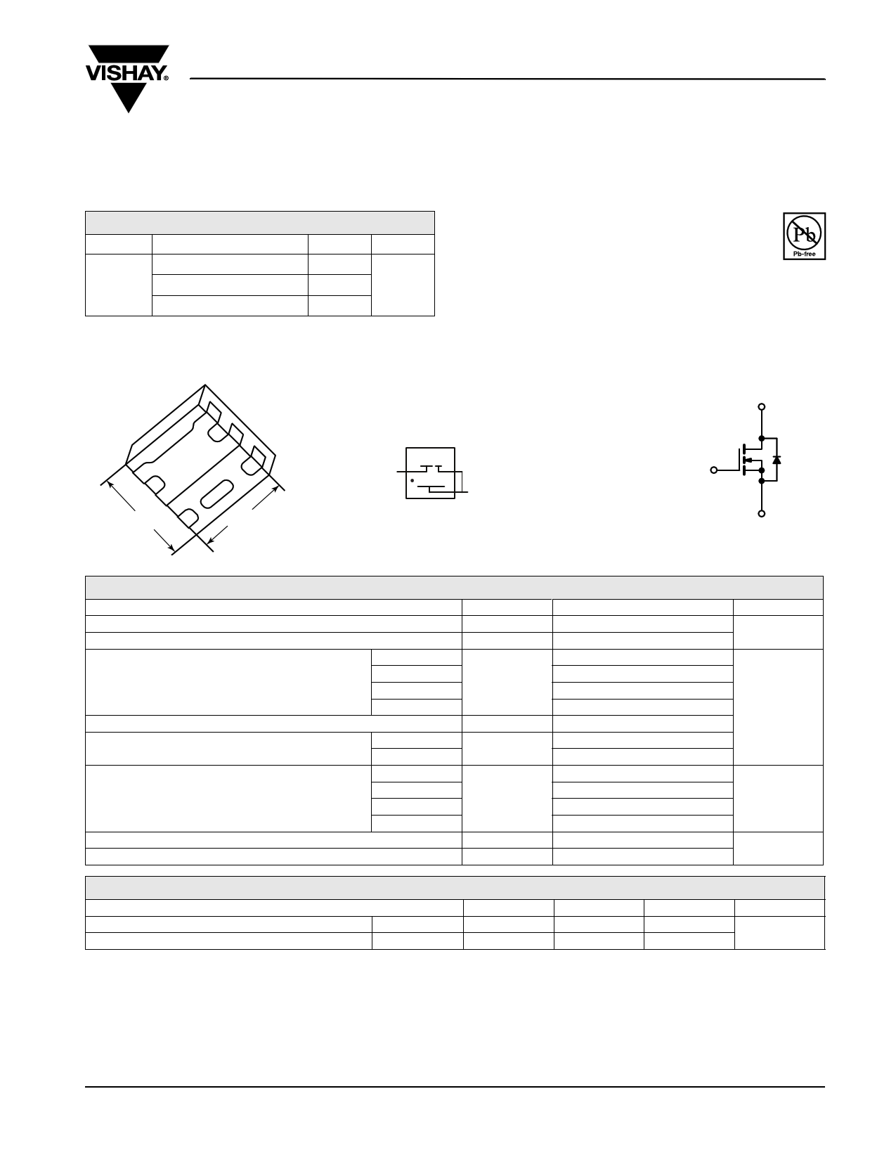
N-Channel 20-V (D-S) MOSFET
SiB412DK
Vishay Siliconix
PRODUCT SUMMARY
VDS (V)
RDS(on) (Ω)
0.034 at VGS = 4.5 V
20 0.040 at VGS = 2.5 V
0.054 at VGS = 1.8 V
PowerPAK SC-75-6L-Single
D
6
D
5
1.60 mm S
4
1
D
2
D
3
G
S
1.60 mm
ID (A)
9a
9a
9a
Qg (Typ.)
6.14 nC
FEATURES
• Halogen-free
• TrenchFET® Power MOSFET
• New Thermally Enhanced PowerPAK®
SC-75 Package
- Small Footprint Area
- Low On-Resistance
RoHS
COMPLIANT
APPLICATIONS
• Load Switch, PA Switch and Battery Switch for Portable
Devices
• DC/DC Converter
D
Marking Code
Part # code
AAX
XXX
Lot Traceability
and Date code
Ordering Information: SiB412DK-T1-GE3 (Lead (Pb)-free and Halogen-free)
G
S
N-Channel MOSFET
ABSOLUTE MAXIMUM RATINGS TA = 25 °C, unless otherwise noted
Parameter
Symbol
Drain-Source Voltage
Gate-Source Voltage
VDS
VGS
TC = 25 °C
Continuous Drain Current (TJ = 150 °C)
TC = 70 °C
TA = 25 °C
ID
TA = 70 °C
Pulsed Drain Current
Continuous Source-Drain Diode Current
TC = 25 °C
TA = 25 °C
IDM
IS
Maximum Power Dissipation
TC = 25 °C
TC = 70 °C
TA = 25 °C
PD
Operating Junction and Storage Temperature Range
Soldering Recommendations (Peak Temperature)d, e
TA = 70 °C
TJ, Tstg
Limit
20
±8
9a
9a
6.6b, c
5.29b, c
20
9a
2b, c
13
8.4
2.4b, c
1.6b, c
- 55 to 150
260
Unit
V
A
W
°C
THERMAL RESISTANCE RATINGS
Parameter
Symbol
Typical
Maximum
Unit
Maximum Junction-to-Ambientb, f
Maximum Junction-to-Case (Drain)
t≤5s
Steady State
RthJA
RthJC
41
7.5
51
°C/W
9.5
Notes:
a. Package limited.
b. Surface Mounted on 1" x 1" FR4 Board.
c. t = 5 s.
d. See Solder Profile (http://www.vishay.com/ppg?73257). The PowerPAK SC-75 is a leadless package. The end of the lead terminal is exposed
copper (not plated) as a result of the singulation process in manufacturing. A solder fillet at the exposed copper tip cannot be guaranteed and
is not required to ensure adequate bottom side solder interconnection.
e. Rework Conditions: manual soldering with a soldering iron is not recommended for leadless components.
f. Maximum under Steady State conditions is 105 °C/W.
Document Number: 70439
S-80515-Rev. C, 10-Mar-08
www.vishay.com
1
1 page 
New Product
TYPICAL CHARACTERISTICS 25 °C, unless otherwise noted
18 16
15
12
12
98
6
4
3
0
0 25 50 75 100 125 150
TC - Case Temperature (°C)
Current Derating*
0
0
SiB412DK
Vishay Siliconix
25 50 75 100 125
TC - Case Temperature (°C)
Power Derating
150
* The power dissipation PD is based on TJ(max) = 150 °C, using junction-to-case thermal resistance, and is more useful in settling the upper
dissipation limit for cases where additional heatsinking is used. It is used to determine the current rating, when this rating falls below the package
limit.
Document Number: 70439
S-80515-Rev. C, 10-Mar-08
www.vishay.com
5
5 Page | ||
| Páginas | Total 7 Páginas | |
| PDF Descargar | [ Datasheet SiB412DK.PDF ] | |
Hoja de datos destacado
| Número de pieza | Descripción | Fabricantes |
| SiB412DK | N-Channel 20-V (D-S) MOSFET | Vishay |
| Número de pieza | Descripción | Fabricantes |
| SLA6805M | High Voltage 3 phase Motor Driver IC. |
Sanken |
| SDC1742 | 12- and 14-Bit Hybrid Synchro / Resolver-to-Digital Converters. |
Analog Devices |
|
DataSheet.es es una pagina web que funciona como un repositorio de manuales o hoja de datos de muchos de los productos más populares, |
| DataSheet.es | 2020 | Privacy Policy | Contacto | Buscar |