|
|
|
PDF AIC1781A Data sheet ( Hoja de datos )
| Número de pieza | AIC1781A | |
| Descripción | Battery Charge Controller | |
| Fabricantes | Analog Intergrations Corporation | |
| Logotipo | ||
Hay una vista previa y un enlace de descarga de AIC1781A (archivo pdf) en la parte inferior de esta página. Total 18 Páginas | ||
|
No Preview Available !
AIC1781A
Battery Charge Controller
n FEATURES
n DESCRIPTION
l Fast Charge Control of NiMH/NiCd Batteries,
even with a Fluctuating Charging Current.
l Fast Charge Termination by: ∆T / ∆t , −∆V ,
0∆V , Safety Timer, Maximum Temperature,
Maximum Voltage.
l Linearly Adjustable ∆T / ∆t Detection Slope and
Safety Timer.
l Adjustable Peak Voltage Timer for 0∆V .
l Battery Voltage Protection Range Selectable.
l Selectable Battery Temperature Protection
Mode.
l Protection against Battery Voltage and Battery
Temperature Faults.
l Selectable LED Display Mode for Battery Status.
l Five Pulsed Trickle Charge Modes.
l Discharge-before-Charge Function Available for
Eliminating Memory Effect.
l Quick and Easy Testing for Production.
l 16-pin DIP or SO Packages.
n APPLICATIONS
Battery Fast Chargers for:
l Mobile Phones.
l Notebook and Laptop Personal Computers.
l Portable Power Tools and Toys.
l Portable Communication Equipments.
l Portable Video & Stereo Equipments.
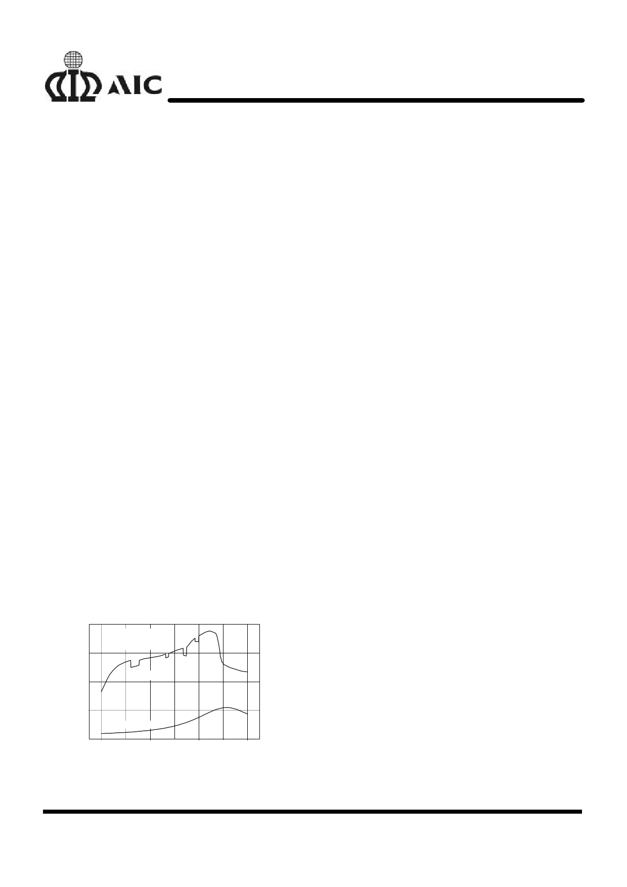
1.55
Charge Current = 600 mA
Cell Capacity = 550 mA
NiMH Battery
1.45
100
80
Cell Voltage
1.35
60
1.25
Temperature
1.15
0
10 20 30 40 50
Charge Time (min.)
40
20
60
Fig. 1
Battery Charging Characteristics Resulting from
an AIC1781A-Controlled Charger with a
Fluctuating Charging Current
The AIC1781A fast charge controller IC is
designed for intelligent charging of NiMH or NiCd
batteries without the risk of overcharge. −∆V
Detection
(-0.25%), 0∆V detection (peak
voltage timer) and ∆T / ∆t detection are the
primary methods employed by the AIC1781A to
terminate fast charge. The fast charge can also be
cut off by maximum battery voltage and maximum
battery temperature detection along with the
safety timer to prevent charging under fault
conditions of the charging system or the battery
itself.
Both ∆T / ∆t and −∆V detection methods have
been proved powerful in terminating fast charging
for NiMH and NiCd batteries. The AIC1781A
utilizes the combination of these two methods to
achieve reliable decision of ending fast charge and
prevent misacting caused by using −∆V detection
alone under certain conditions. Fig. 1 shows an
example of charging curve of a battery charged by
a fluctuating current from a NiMH battery charger,
which uses the AIC1781A controller IC to achieve
optimal charging. This technique, in cooperating
with the 0∆V detection (peak voltage timer), is
particularly suitable for NiMH batteries, whose
voltage drop is hardly significant yet temperature
rises rapidly. The ∆T / ∆t or −∆V detection
circuitry may be disabled independently for
different applications, such as system-integrated
chargers, chargers with varying charge current, or
battery packs lack of temperature sensing
thermistor.
The safety timer period, mode of battery
temperature protection, battery voltage protection
range, pulsed trickle charge duty, and LED display
mode are all adjustable or selectable.
Analog Integrations Corporation
4F, 9 Industry E. 9th Rd, Science-Based Industrial Park, Hsinchu, Taiwan DS-1781AP-01 011604
TEL: 886-3-5772500
FAX: 886-3-5772510 www.analog.com.tw
1
1 page 
AIC1781A
n TYPICAL PERFORMANCE CHARACTERISTICS (TA=25°C, R2=100KΩ, VCC=5V,
refer to Test Circuit)
1.08
1.02
0.96
0.90
0.84
4.4 4.6 4.8 5.0 5.2 5.4
VCC (V)
Fig. 2 Supply Current vs. Supply Voltage
81.5
81.0
80.5
80.0
79.5
79.0
78.5
78.0
4.4 4.6 4.8 5.0 5.2 5.4 5.6
VCC (V)
Fig. 3 Safety Timer vs. Supply Voltage
4.4
4.2
4.0
3.8
3.6
4.4 4.6 4.8 5.0 5.2 5.4
VCC (V)
Fig. 4 LED Flashing Frequency vs.
Supply Voltage
5.6
82
81
80
79
78
77
76
75
0 20 40 60 80
Temperature (°C)
Fig. 6 Safety Timer vs. Temperature
1.05
1.00
0.95
0.90
0.85
0.80
0
20 40 60 80
Temperature (°C)
Fig.5 Supply Current vs. Temperature
5.0
4.8
4.6
4.4
4.2
4.0
3.8
3.6
3.4
-20
0
20 40 60 80
Temperature (°C)
Fig. 7 LED Flashing Frequency vs. Temperature
5
5 Page 
AIC1781A
TABLE 2
BATTERY
CELLS
2~4
3~6
4~8
5~10
6~12
8~16
RA/RB
2
3.3
4.9
6.4
7.8
10.8
RA (KΩ)
240
300
300
300
310
390
RB (KΩ)
120
91
62
47
39
36
For SEL3 < (VCC/2) -0.4V, the suggested divider
resistance of RA and RB for the corresponding
number of battery cells are as below:
TABLE 3
BATTERY
CELLS
2
3
4
5
6
8
10
12
16
RA/RB
1
2
3
4
5
7
9
11
15
RA(KΩ)
240
240
240
300
300
360
360
390
410
RB (KΩ)
240
120
80
75
60
51
40
36
27
Battery Temperature Measurement
The AIC1781A employs a negative temperature
coefficient (NTC) thermistor to measure the
battery’s temperature. The thermistor is inherently
nonlinear with respect to temperature. To reduce
the effect of nonlinearity, a resistor-divider network
in parallel with the thermistor is recommended. A
typical application circuit is shown in Fig. 18.
VBAT
VCC
Rx 5
VCC
4
VTS
C7 AIC1781A
Ry 12
GND
Fig. 18 Battery Temperature Sense Circuit
with a Negative Temperature Coefficient
(NTC) Thermistor
11
11 Page | ||
| Páginas | Total 18 Páginas | |
| PDF Descargar | [ Datasheet AIC1781A.PDF ] | |
Hoja de datos destacado
| Número de pieza | Descripción | Fabricantes |
| AIC1781 | Battery Charge Controller | Analog Intergrations Corporation |
| AIC1781A | Battery Charge Controller | Analog Intergrations Corporation |
| AIC1781CN | Battery Charge Controller | Analog Intergrations Corporation |
| AIC1781CS | Battery Charge Controller | Analog Intergrations Corporation |
| Número de pieza | Descripción | Fabricantes |
| SLA6805M | High Voltage 3 phase Motor Driver IC. |
Sanken |
| SDC1742 | 12- and 14-Bit Hybrid Synchro / Resolver-to-Digital Converters. |
Analog Devices |
|
DataSheet.es es una pagina web que funciona como un repositorio de manuales o hoja de datos de muchos de los productos más populares, |
| DataSheet.es | 2020 | Privacy Policy | Contacto | Buscar |