|
|
|
PDF AUIRLR3636 Data sheet ( Hoja de datos )
| Número de pieza | AUIRLR3636 | |
| Descripción | HEXFET Power MOSFET | |
| Fabricantes | International Rectifier | |
| Logotipo | ||
Hay una vista previa y un enlace de descarga de AUIRLR3636 (archivo pdf) en la parte inferior de esta página. Total 12 Páginas | ||
|
No Preview Available !
AUTOMOTIVE GRADE
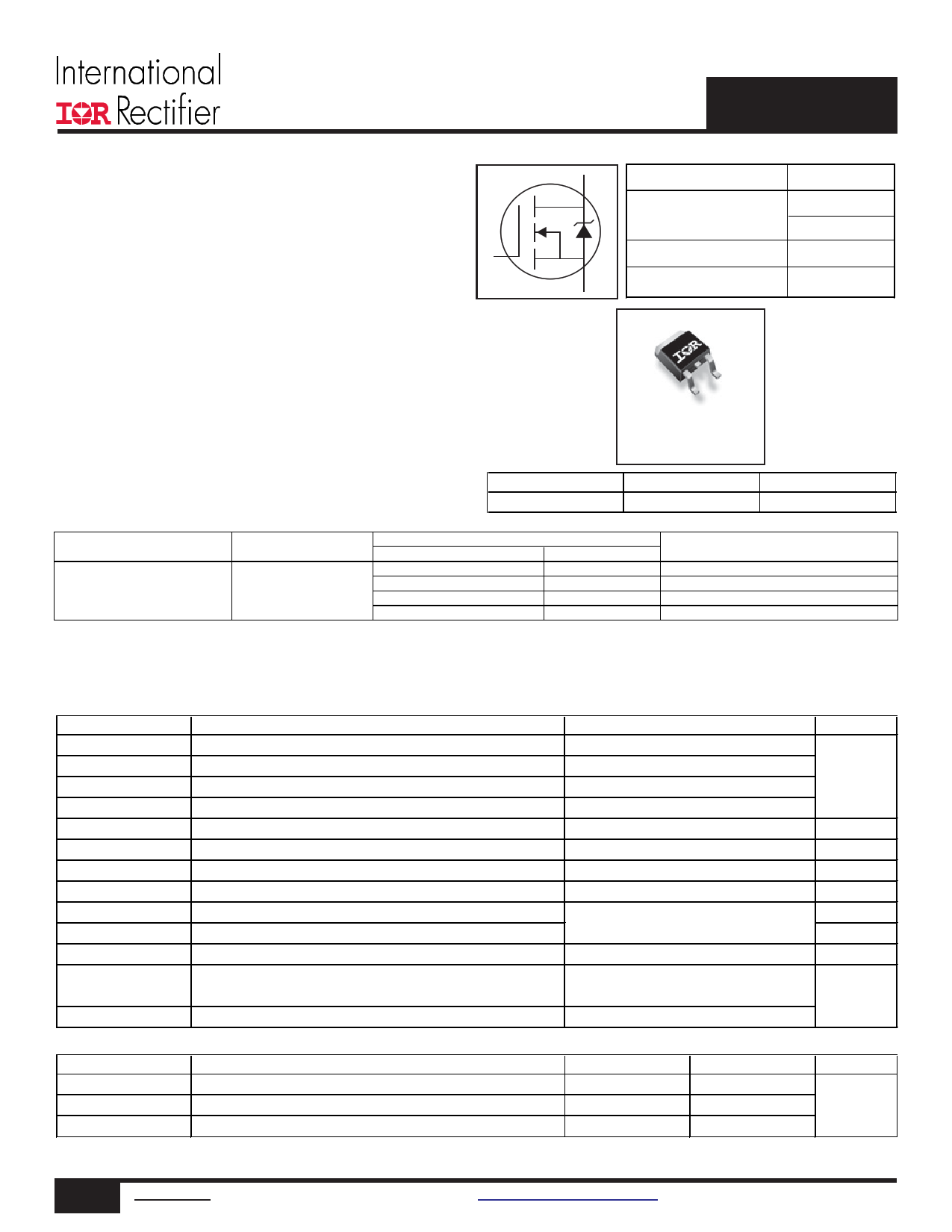
AUIRLR3636
Features
l Advanced Process Technology
l Ultra Low On-Resistance
l Logic Level Gate Drive
l Advanced Process Technology
l 175°C Operating Temperature
l Fast Switching
l Repetitive Avalanche Allowed up to Tjmax
l Lead-Free, RoHS Compliant
l Automotive Qualified *
G
Description
Specifically designed for Automotive applications, this HEXFET®
Power MOSFET utilizes the latest processing techniques to achieve
extremely low on-resistance per silicon area. Additional features of
this design are a 175°C junction operating temperature, fast switching
speed and improved repetitive avalanche rating . These features
combine to make this design an extremely efficient and reliable device
for use in Automotive applications and a wide variety of other applications.
HEXFET® Power MOSFET
D VDSS
RDS(on) typ.
max.
ID (Silicon Limited)
60V
5.4m:
c6.8m:
99A
S ID (Package Limited)
50A
D
G
Gate
S
G
D-Pak
AUIRLR3636
D
Drain
S
Source
Base Part Number
AUIRLR3636
Package Type
D-pak
Standard Pack
Form
Tube
Tape and Reel
Tape and Reel Left
Tape and Reel Right
Quantity
75
2000
3000
3000
Orderable Part Number
AUIRLR3636
AUIRLR3636TR
AUIRLR3636TRL
AUIRLR3636TRR
Absolute Maximum Ratings
Stresses beyond those listed under “Absolute Maximum Ratings” may cause permanent damage to the device. These are stress ratings only; and
functional operation of the device at these or any other condition beyond those indicated in the specifications is not implied. Exposure to absolute-
maximum-rated conditions for extended periods may affect device reliability. The thermal resistance and power dissipation ratings are measured under
board mounted and still air conditions. Ambient temperature (TA) is 25°C, unless otherwise specified.
Symbol
ID @ TC = 25°C
ID @ TC = 100°C
Parameter
Continuous Drain Current, VGS @ 10V (Silicon Limited)
Continuous Drain Current, VGS @ 10V (Silicon Limited)
Max.
99 c
70 c
Units
A
ID @ TC = 25°C
IDM
Continuous Drain Current, VGS @ 10V (Package Limited)
dPulsed Drain Current
50
396
PD @TC = 25°C
Maximum Power Dissipation
143 W
Linear Derating Factor
0.95 W/°C
VGS
EAS
IAR
EAR
dv/dt
Gate-to-Source Voltage
eSingle Pulse Avalanche Energy (Thermally Limited)
dAvalanche Current
dRepetitive Avalanche Energy
fPeak Diode Recovery
±16
170
See Fig.14, 15, 22a, 22b
22
V
mJ
A
mJ
V/ns
TJ
TSTG
Operating Junction and
Storage Temperature Range
-55 to + 175
°C
Soldering Temperature, for 10 seconds (1.6mm from case)
300
Thermal Resistance
RθJC
RθJA
Symbol
Parameter
kJunction-to-Case
jJunction-to-Ambient (PCB Mount)
RθJA Junction-to-Ambient
HEXFET® is a registered trademark of International Rectifier.
*Qualification standards can be found at http://www.irf.com/
Typ.
–––
–––
–––
Max.
1.05
50
110
Units
°C/W
1 www.irf.com © 2014 International Rectifier
Submit Datasheet Feedback
April 09, 2014
1 page 
AUIRLR3636
10
1
D = 0.50
0.1
0.01
0.001
1E-006
0.20
0.10
0.05
0.02
0.01
SINGLE PULSE
( THERMAL RESPONSE )
τJ τJ
τ1 τ1
R1R1
CiC= iτi/Ri/iRi
R2R2
τ2 τ2
R3R3
R4R4
τCτ
Ri (°C/W)
0.02028
0.29406
τi (sec)
0.000011
0.000158
τ3 τ3
τ4 τ4
0.49179 0.001393
0.24336 0.00725
Notes:
1. Duty Factor D = t1/t2
2. Peak Tj = P dm x Zthjc + Tc
1E-005
0.0001
0.001
0.01
0.1
t1 , Rectangular Pulse Duration (sec)
Fig 13. Maximum Effective Transient Thermal Impedance, Junction-to-Case
1000
100
Duty Cycle = Single Pulse
Allowed avalanche Current vs avalanche
pulsewidth, tav, assuming ΔTj = 150°C and
Tstart =25°C (Single Pulse)
0.01
10 0.05
0.10
1
Allowed avalanche Current vs avalanche
pulsewidth, tav, assuming ΔΤ j = 25°C and
Tstart = 150°C.
0.1
1.0E-06
1.0E-05
1.0E-04
1.0E-03
tav (sec)
Fig 14. Typical Avalanche Current vs.Pulsewidth
1.0E-02
1.0E-01
200
TOP
Single Pulse
BOTTOM 1.0% Duty Cycle
ID = 50A
150
100
50
Notes on Repetitive Avalanche Curves , Figures 14, 15:
(For further info, see AN-1005 at www.irf.com)
1. Avalanche failures assumption:
Purely a thermal phenomenon and failure occurs at a temperature far in
excess of Tjmax. This is validated for every part type.
2. Safe operation in Avalanche is allowed as long asTjmax is not exceeded.
3. Equation below based on circuit and waveforms shown in Figures 16a, 16b.
4. PD (ave) = Average power dissipation per single avalanche pulse.
5. BV = Rated breakdown voltage (1.3 factor accounts for voltage increase
during avalanche).
6. Iav = Allowable avalanche current.
7. ΔT = Allowable rise in junction temperature, not to exceed Tjmax (assumed as
25°C in Figure 14, 15).
tav = Average time in avalanche.
D = Duty cycle in avalanche = tav ·f
ZthJC(D, tav) = Transient thermal resistance, see Figures 13)
0
25 50 75 100 125 150 175
Starting TJ , Junction Temperature (°C)
PD (ave) = 1/2 ( 1.3·BV·Iav) = DT/ ZthJC
Iav = 2DT/ [1.3·BV·Zth]
EAS (AR) = PD (ave)·tav
Fig 15. Maximum Avalanche Energy vs. Temperature
5 www.irf.com © 2014 International Rectifier
Submit Datasheet Feedback
April 09, 2014
5 Page 
AUIRLR3636
IMPORTANT NOTICE
Unless specifically designated for the automotive market, International Rectifier Corporation and its subsidiaries (IR) reserve the right to
make corrections, modifications, enhancements, improvements, and other changes to its products and services at any time and to
discontinue any product or services without notice. Part numbers designated with the “AU” prefix follow automotive industry and / or customer
specific requirements with regards to product discontinuance and process change notification. All products are sold subject to IR’s terms
and conditions of sale supplied at the time of order acknowledgment.
IR warrants performance of its hardware products to the specifications applicable at the time of sale in accordance with IR’s standard
warranty. Testing and other quality control techniques are used to the extent IR deems necessary to support this warranty. Except where
mandated by government requirements, testing of all parameters of each product is not necessarily performed.
IR assumes no liability for applications assistance or customer product design. Customers are responsible for their products and applications
using IR components. To minimize the risks with customer products and applications, customers should provide adequate design and
operating safeguards.
Reproduction of IR information in IR data books or data sheets is permissible only if reproduction is without alteration and is accompanied
by all associated warranties, conditions, limitations, and notices. Reproduction of this information with alterations is an unfair and deceptive
business practice. IR is not responsible or liable for such altered documentation. Information of third parties may be subject to additional
restrictions.
Resale of IR products or serviced with statements different from or beyond the parameters stated by IR for that product or service voids all
express and any implied warranties for the associated IR product or service and is an unfair and deceptive business practice. IR is not
responsible or liable for any such statements.
IR products are not designed, intended, or authorized for use as components in systems intended for surgical implant into the body, or in
other applications intended to support or sustain life, or in any other application in which the failure of the IR product could create a situation
where personal injury or death may occur. Should Buyer purchase or use IR products for any such unintended or unauthorized application,
Buyer shall indemnify and hold International Rectifier and its officers, employees, subsidiaries, affiliates, and distributors harmless against
all claims, costs, damages, and expenses, and reasonable attorney fees arising out of, directly or indirectly, any claim of personal injury or
death associated with such unintended or unauthorized use, even if such claim alleges that IR was negligent regarding the design or
manufacture of the product.
IR products are neither designed nor intended for use in military/aerospace applications or environments unless the IR products are
specifically designated by IR as military-grade or “enhanced plastic.” Only products designated by IR as military-grade meet military
specifications. Buyers acknowledge and agree that any such use of IR products which IR has not designated as military-grade is solely
at the Buyer’s risk, and that they are solely responsible for compliance with all legal and regulatory requirements in connection with such
use.
IR products are neither designed nor intended for use in automotive applications or environments unless the specific IR products are
designated by IR as compliant with ISO/TS 16949 requirements and bear a part number including the designation “AU”. Buyers acknowledge
and agree that, if they use any non-designated products in automotive applications, IR will not be responsible for any failure to meet such
requirements.
For technical support, please contact IR’s Technical Assistance Center
http://www.irf.com/technical-info/
WORLD HEADQUARTERS:
233 Kansas St., El Segundo, California 90245
Tel: (310) 252-7105
11 www.irf.com © 2014 International Rectifier
Submit Datasheet Feedback
April 09, 2014
11 Page | ||
| Páginas | Total 12 Páginas | |
| PDF Descargar | [ Datasheet AUIRLR3636.PDF ] | |
Hoja de datos destacado
| Número de pieza | Descripción | Fabricantes |
| AUIRLR3636 | HEXFET Power MOSFET | International Rectifier |
| Número de pieza | Descripción | Fabricantes |
| SLA6805M | High Voltage 3 phase Motor Driver IC. |
Sanken |
| SDC1742 | 12- and 14-Bit Hybrid Synchro / Resolver-to-Digital Converters. |
Analog Devices |
|
DataSheet.es es una pagina web que funciona como un repositorio de manuales o hoja de datos de muchos de los productos más populares, |
| DataSheet.es | 2020 | Privacy Policy | Contacto | Buscar |