|
|
|
PDF A1260 Data sheet ( Hoja de datos )
| Número de pieza | A1260 | |
| Descripción | Chopper Stabilized Precision Vertical Hall-Effect Latch | |
| Fabricantes | Allegro MicroSystems | |
| Logotipo | ||
Hay una vista previa y un enlace de descarga de A1260 (archivo pdf) en la parte inferior de esta página. Total 13 Páginas | ||
|
No Preview Available !
A1260
Chopper-Stabilized Precision Vertical Hall-Effect Latch
FEATURES AND BENEFITS
• AEC-Q100 automotive qualified
• Magnetic sensing parallel to surface of the package
• Highly sensitive switch thresholds
• Symmetrical latch switch points
• Operation from unregulated supply down to 3 V
• Small package sizes
• Automotive grade
□□Output short-circuit protection
□□Resistant to physical stress
□□Reverse-battery protection
□□Solid-state reliability
□□Superior temperature stability
□□Supply voltage Zener clamp
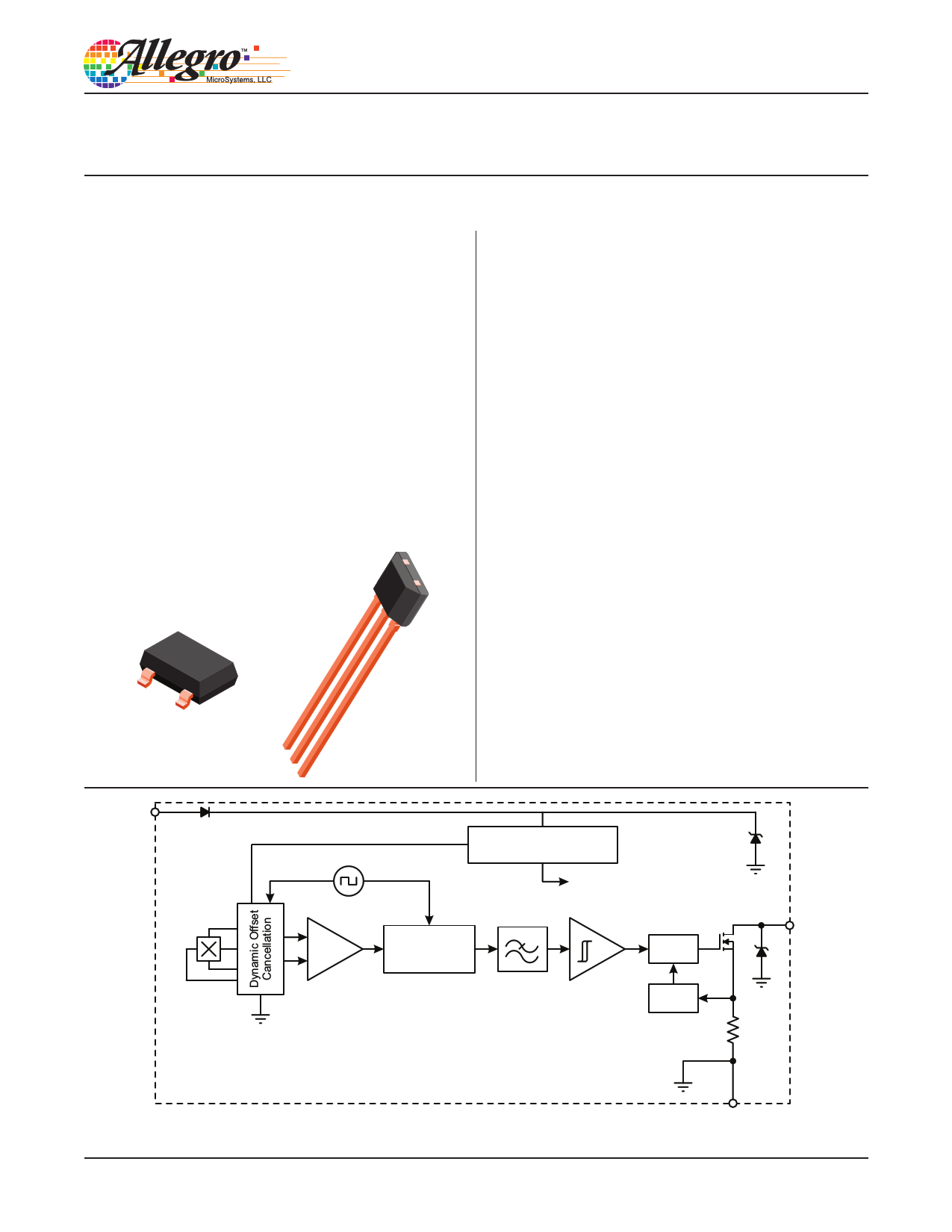
PACKAGES:
3-Pin SOT23-W
(Suffix LH)
3-Pin SIP
(Suffix UA)
Not to scale
DESCRIPTION
The A1260 vertical Hall-effect sensor IC is an extremely
temperature-stable and stress-resistant magnetic-sensing
device ideal for harsh operating environments. The sensor
is actuated by alternating north and south polarity magnetic
fields in plane with the device’s branded face. Two package
options, the SOT23W surface-mount and SIP through-hole,
allow sensing in a variety of orientations with respect to the
mounting position. Superior high-temperature performance
is made possible through dynamic offset cancellation, which
reduces the residual offset voltage normally caused by device
overmolding, temperature dependencies, and thermal stress.
Each device includes on a single silicon chip a voltage regulator,
a Hall-voltage generator, a small-signal amplifier, chopper
stabilization, a Schmitt trigger, and a short-circuit protected
NMOS output to sink up to 25 mA. The on-board regulator
permits operation with supply voltages of 3 to 24 V. The
advantage of operating down to 3 V is that the device can be
used in 3.3 V applications, while allowing additional external
resistance in series with the supply pin for greater protection
against high-voltage transient events.
The output is turned on when a south pole of sufficient strength
perpendicular to the vertical Hall element is present. A north
pole is necessary to turn the output off. Package type LH is a
modified SOT23W surface-mount package that switches with
magnetic fields oriented perpendicularly to the non-leaded side
of the package. The UA package is an ultra-mini SIP, equipped
Continued on next page...
VCC
Vertical
Hall
Hall
Amp
Regulator
To All Subcircuits
Sample, Hold,
& Averaging
Low-Pass
Filter
Control
Current
Limit
VOUT
A1260-DS, Rev. 2
Functional Block Diagram
GND
1 page 
A1260
Chopper-Stabilized Precision
Vertical Hall-Effect Latch
ELECTRICAL OPERATING CHARACTERISTICS
4.0
3.5
3.0
2.5
2.0
1.5
1.0
0.5
0.0
2
6 10 14 18 22
V (V)
CC
Average Supply Current versus Supply Voltage
26
4.0
3.5
3.0
2.5
2.0
1.5
1.0
0.5
0.0
–60 –40 –20 0 20 40 60 80 100 120 140 160
T (ºC)
A
Average Supply Current versus Ambient Temperature
500
450
400
350
300
250
200
150
100
50
0
2
6 10 14 18 22 26
V (V)
CC
Average Low Output Voltage versus Supply Voltage
T (ºC)
A
–40 25
150
500
450
400
350
300
250
200
150
100
50
0
–60 –40 –20 0 20 40 60 80 100 120 140
T (ºC)
A
Average Low Output Voltage versus Ambient
Temperature for IOUT = 20 mA
160
V (V)
CC
3 12
24
Allegro MicroSystems, LLC
115 Northeast Cutoff
Worcester, Massachusetts 01615-0036 U.S.A.
1.508.853.5000; www.allegromicro.com
5
5 Page 
A1260
Chopper-Stabilized Precision
Vertical Hall-Effect Latch
2.90+–00..2100
2.98
+0.12
–0.08
D
0.43
3
PACKAGE OUTLINE DRAWING
For Reference Only – Not for Tooling Use
(Reference DWG-2840)
Dimensions in millimeters – NOT TO SCALE
Dimensions exclusive of mold flash, gate burrs, and dambar protrusions
Exact case and lead configuration at supplier discretion within limits shown
4°±4°
A
0.180+–00..005230
0.96 D
D
1.91+–00..0169
2.40
0.70
12
0.55 REF
8X 10° REF
Branded Face
0.25 BSC
0.25 MIN
1.00
Seating Plane
Gauge Plane
0.95
B PCB Layout Reference View
1.00 ±0.13
NNN
0.95 BSC
0.05
+0.10
–0.05
0.40 ±0.10
A Active Area Depth, 0.28 mm
B Reference land pattern layout
All pads a minimum of 0.20 mm from all adjacent pads; adjust as necessary
to meet application process requirements and PCB layout tolerances
C Branding scale and appearance at supplier discretion
D Hall elements, not to scale
C Standard Branding Reference View
N = Last three digits of device part number
Figure 6: Package LH, 3-Pin SOT23-W
Allegro MicroSystems, LLC
115 Northeast Cutoff
Worcester, Massachusetts 01615-0036 U.S.A.
1.508.853.5000; www.allegromicro.com
11
11 Page | ||
| Páginas | Total 13 Páginas | |
| PDF Descargar | [ Datasheet A1260.PDF ] | |
Hoja de datos destacado
| Número de pieza | Descripción | Fabricantes |
| A1260 | Chopper Stabilized Precision Vertical Hall-Effect Latch | Allegro MicroSystems |
| A1262 | PNP Transistor - 2SA1262 | SavantIC |
| A1262 | Ultrasensitive Hall-Effect Latch | Allegro |
| A1263 | PNP Transistor - 2SA1263 | Toshiba Semiconductor |
| Número de pieza | Descripción | Fabricantes |
| SLA6805M | High Voltage 3 phase Motor Driver IC. |
Sanken |
| SDC1742 | 12- and 14-Bit Hybrid Synchro / Resolver-to-Digital Converters. |
Analog Devices |
|
DataSheet.es es una pagina web que funciona como un repositorio de manuales o hoja de datos de muchos de los productos más populares, |
| DataSheet.es | 2020 | Privacy Policy | Contacto | Buscar |