|
|
|
PDF MAX98371 Data sheet ( Hoja de datos )
| Número de pieza | MAX98371 | |
| Descripción | Digital Input Class D Speaker Amplifier | |
| Fabricantes | Maxim Integrated | |
| Logotipo | ||
Hay una vista previa y un enlace de descarga de MAX98371 (archivo pdf) en la parte inferior de esta página. Total 30 Páginas | ||
|
No Preview Available !
MAX98371
EVALUATION KIT AVAILABLE
Digital Input Class D Speaker Amplifier
with Dynamic Headroom Tracking
General Description
The MAX98371 is a high-efficiency, mono Class D audio
amplifier featuring dynamic headroom tracking (DHT).
DHT automatically optimizes the headroom available to
the Class D amplifier as the power supply voltage var-
ies, due to sudden transients and declining battery life to
maintain a consistent listening experience. A wide 5.5V
to 18V supply range allows the device to reach 19W into
an 8Ω load.
The MAX98371’s flexible digital audio interface (DAI)
supports I2S, left-justified, and TDM formats. The digital
audio interface accepts 32kHz, 44.1kHz, 48kHz, 88.2kHz,
and 96kHz sample rates with 16-/24-/32-bit data sup-
ported for all data formats. In TDM mode, the device can
support up to 16 channels of audio data. A unique clock-
ing structure eliminates the need for an external MCLK
signal that is typically needed for PCM communication.
This reduces pin count and simplifies board layout.
Active emissions limiting with edge rate control minimizes
EMI, and eliminates the need for output filtering found in
traditional Class D devices.
An 8-bit PVDD supply voltage ADC enables the Dynamic
Headroom Tracking circuit. DHT optimizes audio program
peak behavior as the supply voltage varies and provides
flexible user-defined parameters.
Thermal foldback protection ensures robust behavior
when the thermal limits of the device are exercised. The
circuit can be enabled to automatically reduce the output
power above a user specified temperature. This allows for
uninterrupted music playback even at high ambient tem-
peratures. Traditional thermal protection is also available
in addition to robust overcurrent protection.
All MAX98371 control is performed using a standard
2-wire, I2C interface. One of sixteen slave addresses can
be selected through two, four-level address pins. The IC
is available in a 0.4mm pitch, 30-bump WLP package. It is
specified over the extended, -40°C to +85°C temperature
range.
Applications
●● Tablets
●● Notebook Computers
●● Soundbars
Benefits and Features
●● Wide Supply Range (5.5V to 18V)
●● Dynamic Headroom Tracking Maintains a Consistent
Listening Experience
●● Integrated Thermal Foldback Allows Robust
Operation in a WLP Package
●● Remote Output Sensing Allows Up to 20dB THD+N
Improvement When Ferrites Are Used
●● Class D Edge Rate Control Enables Filterless
Operation
●● 110dB A-Weighted Dynamic Range
●● Output Power at 1% THD+N:
• 15.7W into 8Ω, VPVDD = 17V
• 13.2W into 4Ω, VPVDD = 12V
●● Output Power at 10% THD+N
• 19W into 8Ω, VPVDD = 17V
• 15.8W into 4Ω, VPVDD = 12V
●● Speaker Amplifier Efficiency
• 91% at 10W into 8Ω, VPVDD = 12V
• 81% at 15W into 4Ω, VPVDD = 12V
●● Extensive Click-and-Pop Suppression
●● Space Saving, 30-Bump WLP Package (2.1mm x
2.6mm x 0.6mm, 0.4mm Pitch)
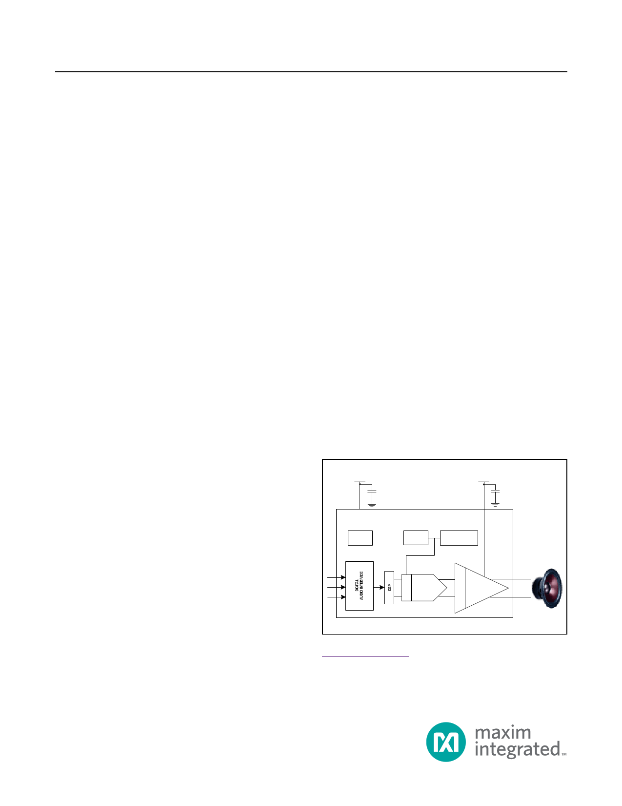
Simplified Block Diagram
DVDD
PVDD
MAX98371
I2C
DHT
THERMAL
FOLDBACK
D
V
O
DAC
L
P
G CLASS D
A
Ordering Information appears at end of data sheet.
19-7537; Rev 0; 3/15
1 page 
MAX98371
Digital Input Class D Speaker Amplifier
with Dynamic Headroom Tracking
LIST OF TABLES (CONTINUED)
Table 7. Configuration for Digital Audio Interface Format . . . . . . . . . . . . . . . . . . . . . . . . . . . . . . . . . . . . . . . . . . . . . . . 42
Table 8. TDM Channel Selection for Mono Replay . . . . . . . . . . . . . . . . . . . . . . . . . . . . . . . . . . . . . . . . . . . . . . . . . . . 44
Table 9. Digital Highpass Filter . . . . . . . . . . . . . . . . . . . . . . . . . . . . . . . . . . . . . . . . . . . . . . . . . . . . . . . . . . . . . . . . . . . 47
Table 10. Biquad Filter Coefficient Registers . . . . . . . . . . . . . . . . . . . . . . . . . . . . . . . . . . . . . . . . . . . . . . . . . . . . . . . . 48
Table 11. Signal Path Delay . . . . . . . . . . . . . . . . . . . . . . . . . . . . . . . . . . . . . . . . . . . . . . . . . . . . . . . . . . . . . . . . . . . . . 48
Table 12. PVDD Measurement ADC . . . . . . . . . . . . . . . . . . . . . . . . . . . . . . . . . . . . . . . . . . . . . . . . . . . . . . . . . . . . . . . 49
Table 13. Digital Volume Ramping and Digital Volume . . . . . . . . . . . . . . . . . . . . . . . . . . . . . . . . . . . . . . . . . . . . . . . . 49
Table 14. Digital Gain Settings and Output Voltage Scaling . . . . . . . . . . . . . . . . . . . . . . . . . . . . . . . . . . . . . . . . . . . . 50
Table 15. Speaker Gain Minimum Voltage . . . . . . . . . . . . . . . . . . . . . . . . . . . . . . . . . . . . . . . . . . . . . . . . . . . . . . . . . . 54
Table 16. Dynamic Headroom Tracking Attack Settings . . . . . . . . . . . . . . . . . . . . . . . . . . . . . . . . . . . . . . . . . . . . . . . 59
Table 17. Dynamic Headroom Tracking Release Settings . . . . . . . . . . . . . . . . . . . . . . . . . . . . . . . . . . . . . . . . . . . . . . 60
Table 18. Dynamic Gain Enables . . . . . . . . . . . . . . . . . . . . . . . . . . . . . . . . . . . . . . . . . . . . . . . . . . . . . . . . . . . . . . . . . 60
Table 19. Limiter Threshold Select . . . . . . . . . . . . . . . . . . . . . . . . . . . . . . . . . . . . . . . . . . . . . . . . . . . . . . . . . . . . . . . . 60
Table 20. Manual Limiter Threshold Settings . . . . . . . . . . . . . . . . . . . . . . . . . . . . . . . . . . . . . . . . . . . . . . . . . . . . . . . . 61
Table 21. Limiter Threshold . . . . . . . . . . . . . . . . . . . . . . . . . . . . . . . . . . . . . . . . . . . . . . . . . . . . . . . . . . . . . . . . . . . . . . 61
Table 22. Limiter Attack and Release Settings . . . . . . . . . . . . . . . . . . . . . . . . . . . . . . . . . . . . . . . . . . . . . . . . . . . . . . . 62
Table 23. Thermal ADC Measurements . . . . . . . . . . . . . . . . . . . . . . . . . . . . . . . . . . . . . . . . . . . . . . . . . . . . . . . . . . . . 62
Table 24. Thermal Foldback Settings . . . . . . . . . . . . . . . . . . . . . . . . . . . . . . . . . . . . . . . . . . . . . . . . . . . . . . . . . . . . . . 63
Table 25. Thermal Foldback Enable . . . . . . . . . . . . . . . . . . . . . . . . . . . . . . . . . . . . . . . . . . . . . . . . . . . . . . . . . . . . . . . 63
Table 26. DHT INFO . . . . . . . . . . . . . . . . . . . . . . . . . . . . . . . . . . . . . . . . . . . . . . . . . . . . . . . . . . . . . . . . . . . . . . . . . . . 64
Table 28. Thermal and DHT Link Enables . . . . . . . . . . . . . . . . . . . . . . . . . . . . . . . . . . . . . . . . . . . . . . . . . . . . . . . . . . 64
Table 27. THERM INFO . . . . . . . . . . . . . . . . . . . . . . . . . . . . . . . . . . . . . . . . . . . . . . . . . . . . . . . . . . . . . . . . . . . . . . . . 64
Table 29. InterChip Communication Configuration . . . . . . . . . . . . . . . . . . . . . . . . . . . . . . . . . . . . . . . . . . . . . . . . . . . . 65
Table 30. DOUT Double Data Drive Mode . . . . . . . . . . . . . . . . . . . . . . . . . . . . . . . . . . . . . . . . . . . . . . . . . . . . . . . . . . 66
Table 31. DOUT DHT Receive Channel Configuration . . . . . . . . . . . . . . . . . . . . . . . . . . . . . . . . . . . . . . . . . . . . . . . . . 67
Table 32. DOUT Thermal Foldback Receive Channel Configuration . . . . . . . . . . . . . . . . . . . . . . . . . . . . . . . . . . . . . . 68
Table 33. DOUT Thermal Foldback Receive Channel Configuration . . . . . . . . . . . . . . . . . . . . . . . . . . . . . . . . . . . . . . 69
Table 34. Extra BCLK Cycle Configuration . . . . . . . . . . . . . . . . . . . . . . . . . . . . . . . . . . . . . . . . . . . . . . . . . . . . . . . . . 70
Table 35. Manual HIZ Mode Configuration . . . . . . . . . . . . . . . . . . . . . . . . . . . . . . . . . . . . . . . . . . . . . . . . . . . . . . . . . . 70
Table 36. Speaker Configuration . . . . . . . . . . . . . . . . . . . . . . . . . . . . . . . . . . . . . . . . . . . . . . . . . . . . . . . . . . . . . . . . . 71
Table 37. Clock Monitor Configuration . . . . . . . . . . . . . . . . . . . . . . . . . . . . . . . . . . . . . . . . . . . . . . . . . . . . . . . . . . . . . 73
Table 38. Reset Register . . . . . . . . . . . . . . . . . . . . . . . . . . . . . . . . . . . . . . . . . . . . . . . . . . . . . . . . . . . . . . . . . . . . . . . . 73
Table 39. Global Enable Register . . . . . . . . . . . . . . . . . . . . . . . . . . . . . . . . . . . . . . . . . . . . . . . . . . . . . . . . . . . . . . . . . 73
Table 40. ADDR I2C Address Select . . . . . . . . . . . . . . . . . . . . . . . . . . . . . . . . . . . . . . . . . . . . . . . . . . . . . . . . . . . . . . 77
Table 41. Recommended External Components . . . . . . . . . . . . . . . . . . . . . . . . . . . . . . . . . . . . . . . . . . . . . . . . . . . . . 78
www.maximintegrated.com
Maxim Integrated │ 5
5 Page 
MAX98371
Digital Input Class D Speaker Amplifier
with Dynamic Headroom Tracking
Electrical Characteristics (continued)
(VPVDD = 12V, VDVDD = VRESET = 1.8V, VGND = 0V, CPVDD = 1x 220µF, 2x 10µF, 2x 0.1µF, CREFC = 1µF, CDVDD = 1µF, ZSPK = open,
AC measurement bandwidth 20Hz to 22kHz, fS = 48kHz, 24-bit data, TA = TMIN to TMAX, unless, otherwise noted. Typical values are at
TA = +25°C.) (Note 2)
PARAMETER
SYMBOL
CONDITION
MIN
TYP
MAX UNITS
ADC Lowpass Filter
Stopband Frequency
ADC Programmable
Lowpass Filter
DIGITAL I/O CHARACTERISTICS
DIN, BCLK, LRCLK, ADDR_, RESET
Input Voltage High
VIH
-40dB limit
PVDD_ADC_BW[1:0] = 0x1
PVDD_ADC_BW[1:0] = 0x2
PVDD_ADC_BW[1:0] = 0x3
Input Voltage Low
Input Leakage Current
Input Capacitance
INPUT (SDA, SCL)
VIL
IIH, IIL
CIN
0.167
x fS
2
20
200
Hz
Hz
0.7 x
VDVDD
V
0.3 x
VDVDD
V
-1 +1 µA
3 pF
Input Voltage High
VIH
Input Voltage Low
VIL
Input Hysteresis
Input Capacitance
Input Leakage Current
OUTPUT (SDA, IRQ)
VHYS
CIN
IIH, IIL
TA = +25°C, input high
Output Low Voltage
VOL
ISINK = 3mA
Output Current
IOL
DIGITAL AUDIO INTERFACE TIMING CHARACTERISTICS
GLOBAL
LRCLK Frequency Range
fLRCLK All DAI operating modes
Word Length
All DAI operating modes
0.7 x
VDVDD
-1
32
BCLK Duty Cycle
Maximum BCLK/LRCLK
Input Jitter
Maximum jitter with RMS jitter below 40kHz
minimal performance
degradation
RMS jitter above 40kHz
45
V
0.3 x
VDVDD
V
200 mV
3 pF
+1 µA
0.4 V
13 mA
96 kHz
16
24 bits
32
55 %
0.5
ns
0.9
www.maximintegrated.com
Maxim Integrated │ 11
11 Page | ||
| Páginas | Total 30 Páginas | |
| PDF Descargar | [ Datasheet MAX98371.PDF ] | |
Hoja de datos destacado
| Número de pieza | Descripción | Fabricantes |
| MAX98371 | Digital Input Class D Speaker Amplifier | Maxim Integrated |
| MAX98372 | Digital Input Class D Amplifier | Maxim Integrated |
| Número de pieza | Descripción | Fabricantes |
| SLA6805M | High Voltage 3 phase Motor Driver IC. |
Sanken |
| SDC1742 | 12- and 14-Bit Hybrid Synchro / Resolver-to-Digital Converters. |
Analog Devices |
|
DataSheet.es es una pagina web que funciona como un repositorio de manuales o hoja de datos de muchos de los productos más populares, |
| DataSheet.es | 2020 | Privacy Policy | Contacto | Buscar |