|
|
|
PDF MCP73863 Data sheet ( Hoja de datos )
| Número de pieza | MCP73863 | |
| Descripción | Advanced Single or Dual Cell / Fully Integrated Li-Ion / Li-Polymer Charge Management Controllers | |
| Fabricantes | Microchip Technology | |
| Logotipo | ||
Hay una vista previa y un enlace de descarga de MCP73863 (archivo pdf) en la parte inferior de esta página. Total 30 Páginas | ||
|
No Preview Available !
MCP73861/2/3/4
Advanced Single or Dual Cell, Fully Integrated Li-Ion/Li-Polymer
Charge Management Controllers
Features
• Linear Charge Management Controllers
- Integrated Pass Transistor
- Integrated Current Sense
- Reverse-Blocking Protection
• High-Accuracy Preset Voltage Regulation: + 0.5%
• Four Selectable Voltage Regulation Options:
- 4.1V, 4.2V – MCP73861/3
- 8.2V, 8.4V – MCP73862/4
• Programmable Charge Current: 1.2A Maximum
• Programmable Safety Charge Timers
• Preconditioning of Deeply Depleted Cells
• Automatic End-of-Charge Control
• Optional Continuous Cell Temperature Monitoring
• Charge Status Output for Direct LED Drive
• Fault Output for Direct LED Drive
• Automatic Power-Down
• Thermal Regulation
• Temperature Range: -40°C to +85°C
• Packaging: 16-Pin, 4 x 4 QFN
16-Pin SOIC
Applications
• Lithium-Ion/Lithium-Polymer Battery Chargers
• Personal Data Assistants (PDAs)
• Cellular Telephones
• Hand-Held Instruments
• Cradle Chargers
• Digital Cameras
• MP3 Players
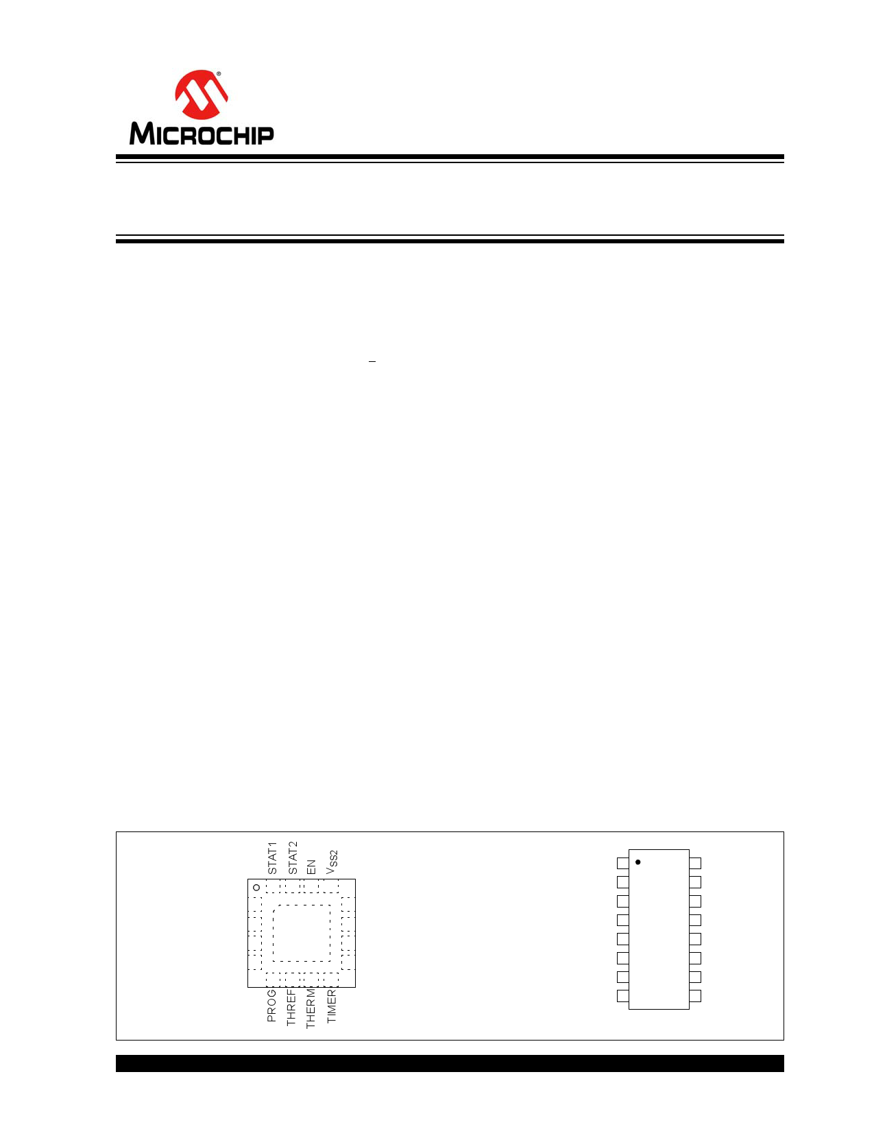
Package Types
16-Pin QFN
16 15 14 13
VSET 1
12 VBAT3
VDD2 2
VDD2 3
EP 11 VBAT2
17 10 VBAT1
VSS1 4
9 VSS3
567 8
Description
The MCP7386X family of devices features highly
advanced linear charge management controllers for
use in space-limited, cost-sensitive applications. The
devices combine high-accuracy, constant voltage and
current regulation, cell preconditioning, cell tempera-
ture monitoring, advanced safety timers, automatic
charge termination, internal current sensing, reverse-
blocking protection, charge status and fault indication
in either a space-saving 16-pin 4 x 4 QFN package, or
a 16-pin SOIC package. The MCP7386X provides a
complete, fully functional, stand-alone charge manage-
ment solution with a minimum number of external
components.
The MCP73861/3 is intended for applications utilizing
single-cell Lithium-Ion or Lithium-Polymer battery
packs, while the MCP73862/4 is intended for dual
series cell Lithium-Ion or Lithium-Polymer battery
packs. The MCP73861/3 has two selectable
voltage-regulation options available (4.1V and 4.2V),
for use with either coke or graphite anodes and operate
with an input voltage range of 4.5V to 12V. The
MCP73862/4 has two selectable voltage-regulation
options available (8.2V and 8.4V), for use with coke or
graphite anodes, and operate with an input voltage
range of 8.7V to 12V.
The MCP73861/2 and MCP73863/4 differ only in the
function of the charge status output (STAT1) when a
charge cycle has been completed. The MCP73861/2
flashes the output, while the MCP73863/4 turns the
output off. Refer to Section 5.2.1 “Charge Status
Outputs (STAT1, STAT2)”.
The MCP7386X family of devices are fully specified
over the ambient temperature range of -40°C to +85°C.
16-Pin SOIC
STAT2 1
STAT1 2
VSET 3
VDD1 4
VDD2 5
VSS1 6
PROG 7
THREF 8
16 EN
15 VSS2
14 VBAT3
13 VBAT2
12 VBAT1
11 VSS3
10 TIMER
9 THERM
2011 Microchip Technology Inc.
DS21893E-page 1
1 page 
MCP73861/2/3/4
DC CHARACTERISTICS (CONTINUED)
Electrical Specifications: Unless otherwise indicated, all limits apply for VDD= [VREG(typ.) + 0.3V] to 12V,
TA = -40°C to +85°C. Typical values are at +25°C, VDD = [VREG (typ.) + 1.0V]
Parameters
Sym
Min
Typ
Max
Unit
s
Thermal Shutdown
Die Temperature
Die Temperature
Hysteresis
TSD — 155 — °C
TSDHYS
—
10
— °C
Conditions
AC CHARACTERISTICS
Electrical Specifications: Unless otherwise indicated, all limits apply for VDD = [VREG (typ.) + 0.3V] to 12V,
TA = -40°C to +85°C. Typical values are at +25°C, VDD = [VREG (typ.) + 1.0V]
Parameters
Sym
Min Typ Max Units
Conditions
UVLO Start Delay
Current Regulation
tSTART
Transition Time Out of
Preconditioning
tDELAY
Current Rise Time Out of
Preconditioning
tRISE
Fast Charge Safety Timer
Period
tFAST
Preconditioning Current Regulation
Preconditioning Charge Safety
Timer Period
tPRECON
Charge Termination
Elapsed Time Termination
Period
tTERM
Status Indicators
Status Output turn-off
Status Output turn-on
tOFF
tON
— — 5 ms VDD Low-to-High
— — 1 ms VBAT < VPTH to VBAT > VPTH
— — 1 ms IOUT Rising to 90% of IREG
1.1 1.5 1.9 Hours CTIMER = 0.1 µF
45 60 75 Minutes CTIMER = 0.1 µF
2.2 3 3.8 Hours CTIMER = 0.1 µF
— — 200 µs ISINK = 1 mA to 0 mA
— — 200 µs ISINK = 0 mA to 1 mA
TEMPERATURE SPECIFICATIONS
Electrical Specifications: Unless otherwise indicated, all limits apply for VDD = [VREG (typ.) + 0.3V] to 12V.
Typical values are at +25°C, VDD = [VREG (typ.) + 1.0V]
Parameters
Sym
Min Typ Max
Units
Conditions
Temperature Ranges
Specified Temperature Range
Operating Temperature Range
Storage Temperature Range
Thermal Package Resistances
Thermal Resistance, 16-lead,
4 mm x 4 mm QFN
Thermal Resistance, 16-lead SOIC
TA -40 — +85 °C
TJ -40 — +125 °C
TA -65 — +150 °C
JA — 47 — °C/W 4-Layer JC51-7 Standard Board,
Natural Convection
JA
— 86.1 —
°C/W 4-Layer JC51-7 Standard Board,
Natural Convection
2011 Microchip Technology Inc.
DS21893E-page 5
5 Page 
MCP73861/2/3/4
NOTE: Unless otherwise indicated, VDD = [VREG(typ.) + 1V], IOUT = 10 mA and TA= +25°C, Constant-voltage mode.
VDD
VDD
VBAT
MCP73861
VDD Stepped from 5.2V to 6.2V
IOUT = 10 mA
COUT = 10 µF, X7R, Ceramic
FIGURE 2-25:
Line Transient Response.
MCP73861
VDD 5.2V
COUT = 10 µF, X7R, Ceramic
VBAT
100 mA IOUT
10 mA
MCP73861
VDD Stepped from 5.2V to 6.2V
IOUT = 500 mA
COUT = 10 µF, X7R, Ceramic
VBAT
FIGURE 2-28:
Line Transient Response.
MCP73861
VDD 5.2V
COUT = 10 µF, X7R, Ceramic
VBAT
500 mA IOUT
10 mA
FIGURE 2-26:
Load Transient Response.
0 MCP73861
-10 VDD = 5.2V
-20
VAC = 100 mVp-p
IOUT = 10 mA
-30 COUT = 10 μF, Ceramic
-40
-50
-60
-70
-80
0.01
0.1
1
10
Frequency (kHz)
100
1000
FIGURE 2-27:
Rejection.
Power Supply Ripple
FIGURE 2-29:
Load Transient Response.
0
-10
-20
-30
-40
-50
-60
-70
-80
0.01
0.1
FIGURE 2-30:
Rejection.
MCP73861
VDD = 5.2V
VAC = 100 mVp-p
IOUT = 100 mA
COUT = 10 μF, X7R, Ceramic
1 10
Frequency (kHz)
100
1000
Power Supply Ripple
2011 Microchip Technology Inc.
DS21893E-page 11
11 Page | ||
| Páginas | Total 30 Páginas | |
| PDF Descargar | [ Datasheet MCP73863.PDF ] | |
Hoja de datos destacado
| Número de pieza | Descripción | Fabricantes |
| MCP73861 | Advanced Single or Dual Cell / Fully Integrated Li-Ion / Li-Polymer Charge Management Controllers | Microchip Technology |
| MCP73862 | Advanced Single or Dual Cell / Fully Integrated Li-Ion / Li-Polymer Charge Management Controllers | Microchip Technology |
| MCP73863 | Advanced Single or Dual Cell / Fully Integrated Li-Ion / Li-Polymer Charge Management Controllers | Microchip Technology |
| MCP73864 | Advanced Single or Dual Cell / Fully Integrated Li-Ion / Li-Polymer Charge Management Controllers | Microchip Technology |
| Número de pieza | Descripción | Fabricantes |
| SLA6805M | High Voltage 3 phase Motor Driver IC. |
Sanken |
| SDC1742 | 12- and 14-Bit Hybrid Synchro / Resolver-to-Digital Converters. |
Analog Devices |
|
DataSheet.es es una pagina web que funciona como un repositorio de manuales o hoja de datos de muchos de los productos más populares, |
| DataSheet.es | 2020 | Privacy Policy | Contacto | Buscar |