No Preview Available !

APPLICATION
Buck Converter High Side Switch
�DC motor control , Ups ...etc , & other Application
VDSS
55V
RDS(ON) Max.
17.5mȍ
PIN CONFIGURATION
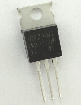
TO-220
Front View
ID
50A
IRFZ44N
N-CHANNEL Power MOSFET
FEATURES
�Ultra Low ON Resistance
�Low Gate Charge
Dynamic dv/dt Rating
Inductive Switching Curves
Peak Current vs Pulse Width Curve
SYMBOL
D
G
S
12 3
ʳ
ABSOLUTE MAXIMUM RATINGS
N-Channel MOSFET
Rating
Drain to Source Voltage
Drain to Current Ё Continuous Tc = 25к, VGS@10V
Ё Continuous Tc = 100к, VGS@10V
Ё Pulsed Tc = 25к, VGS@10V (Note 1)
Gate-to-Source Voltage Ё Continue
Total Power Dissipation
Derating Factor above 25к
Peak Diode Recovery dv/dt (Note 3)
Operating Junction and Storage Temperature Range
Repetitive Avalanche Energy (Note 1)
Maximum Lead Temperature for Soldering Purposes
Maximum Package Body for 10 seconds
Avalanche Current (Note 1)
Symbol
VDSS
ID
ID
IDM
VGS
PD
dv/dt
TJ, TSTG
EAR
TL
TPKG
IAR
Value
55
50
35
160
±20
.94
0.63
5.0
-55 to 175
9.4
300
260
25
Unit
V
A
V
W
W/к
V/ns
к
mJ
к
к
A
THERMAL RESISTANCE
Symbol
Parameter
RșJC
Junction-to-case
Min Typ
RșJA Junction-to-ambient
Max
1.5
62
Units
к/W
к/W
Test Conditions
Water cooled heatsink, PD adjusted for a peak junction
temperature of +175к
1 cubic foot chamber, free air
www.magic-matsu.com
Page 1

Figure 11. Typical Breakdown Voltage vs
Junction Temperature
1.20
1.15
1.10
1.05
1.00
0.95 VGS = 0V
0.90 ID = 250 µA
-75 -50 -25 0.0 25 50 75 100 125 150 175
TJ, Junction Temperature (oC)
Figure 13. Maximum Forward Bias Safe
Operating Area
1000
OPERATION IN THIS AREA MAY BE LIMITED BY R
DS(ON)
10µs
100
100µ
10
TJ = MAX RATED, TC = 25 oC
1 Single Pulse
1 10
1.0m
10 ms
DC
100
VDS, Drain-to-Source Voltage (V)
IRFZ44N
N-CHANNEL Power MOSFET
Figure 12. Typical Threshold Voltage vs
Junction Temperature
1.2
1.1
1.0
0.9
0.8
0.7
0.6 VGS = VDS
ID = 250 µA
0.5
-75 -50 -25 0.0 25 50 75 100 125 150 175
TJ, Junction Temperature (oC)
Figure 14. Typical Capacitance
vs Drain-to-Source Voltage
3000
2500
2000
VGS = 0V, f = 1MHz
Ciss = Cgs + Cgd
Ciss Coss # Cds + Cgd
Crss = Cgd
1500
1000
Coss
500
0
0.01
0.1
Crss
1 10
100
VDS, Drain Voltage (V)
Figure 15. Typical Gate Charge
vs Gate-to-Source Voltage
12
10
VDS=45V
8 VDS=30V
VDS=15V
6
4
2
ID = 59A
0
0 5 10 15 20 25 30 35 40
QG,Total Gate Charge (nC)
www.magic-matsu.com
Figure 16. Typical Body Diode Transfer
Characteristics
180
160
140
120
100
80
60
40
20
0
0.3
150 oC
25 oC
-55 oC
VGS = 0V
0.5 0.7 0.9 1.1 1.3
VSD, Source-to-Drain Voltage (V)
Page 5


