|
|
|
PDF AS1324 Data sheet ( Hoja de datos )
| Número de pieza | AS1324 | |
| Descripción | 600mA Synchronous DC/DC Converter | |
| Fabricantes | ams | |
| Logotipo | ||
Hay una vista previa y un enlace de descarga de AS1324 (archivo pdf) en la parte inferior de esta página. Total 21 Páginas | ||
|
No Preview Available !
AS1324
1.5MHz, 600mA Synchronous DC/DC Converter
1 General Description
The AS1324 is a high-efficiency, constant-frequency synchronous
buck converter available in adjustable- and fixed-voltage versions.
The wide input voltage range (2.7V to 5.5V), automatic powersave
mode and minimal external component requirements make the
AS1324 perfect for any single Li-Ion battery-powered application.
Typical supply current with no load is 30µA and decreases to ≤1µA
in shutdown mode.
The AS1324 is available as the standard versions listed in Table 1.
Table 1. Standard Versions
Model
Output Voltage
AS1324-AD
Adjustable via External Resistors
AS1324-12
Fixed: 1.2V
AS1324-15
Fixed: 1.5V
AS1324-18
Fixed: 1.8V
An internal synchronous switch increases efficiency and eliminates
the need for an external Schottky diode. The internally fixed
switching frequency (1.5MHz) allows for the use of small surface
mount external components.
Very low output voltages can be delivered with the internal 0.6V
feedback reference voltage.
The AS1324 is available in a 5-pin TSOT-23 package.
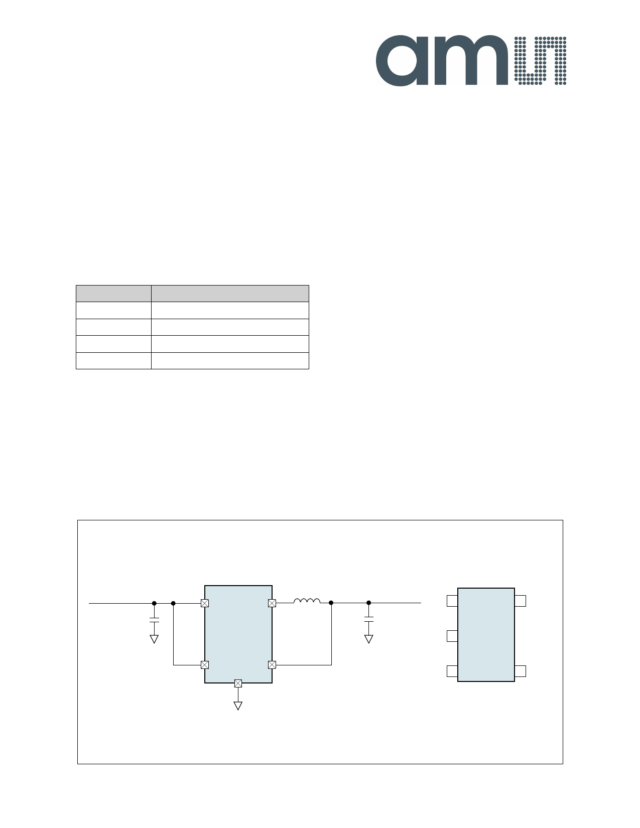
Figure 1. Typical Application Diagram – High Efficiency Step
Down Converter
2 Key Features
High Efficiency: Up to 96%
Output Current: 600mA
Input Voltage Range: 2.7V to 5.5V
Constant Frequency Operation: 1.5MHz
Variable- and Fixed-Output Voltages
No Schottky Diode Required
Automatic Powersave Operation
Low Quiescent Current: 30µA
Internal Reference: 0.6V
Shutdown Mode Supply Current: ≤1µA
Thermal Protection
5-pin TSOT-23 Package
3 Applications
The device is ideal for mobile communication devices, laptops and
PDAs, ultra-low-power systems, threshold detectors/discriminators,
telemetry and remote systems, medical instruments, or any other
space-limited application with low power-consumption requirements.
VIN = 2.7V to 5.5V
CIN
10µF
4 3 4.7µH
VIN SW
AS1324-18
15
EN VOUT
2 GND
VOUT = 1.8V, 600mA
COUT
10µF
EN 1
5 VOUT
AS1324-18
GND 2
SW 3
4 VIN
www.ams.com/DC-DC_Step-Up/AS1324
Revision 1.06
1 - 21
1 page 
AS1324
Datasheet - Typical Operating Characteristics
7 Typical Operating Characteristics
Parts used for measurement: 4.7µH (MOS6020-472) Inductor, 10µF (GRM188R60J106ME47) CIN and COUT.
Figure 3. Efficiency vs. Input Voltage; VOUT = 1.8V
95
90
85
80
75
70
65
60 IOUT = 600mA
IOUT = 100mA
55 IOUT = 10mA
IOUT = 1mA
50
2.7 3.1 3.5 3.9 4.3 4.7 5.1 5.5
Input Voltage (V)
Figure 4. Efficiency vs. Output Current; VOUT = 1.2V
100
95
90
85
80
75
70
65
60
55
50
1
VIN = 2.5V
VIN = 2.7V
VIN = 3.7V
VIN = 4.2V
VIN = 5.5V
10 100
Output Current (mA)
1000
Figure 5. Efficiency vs. Output Current; VOUT = 1.5V
100
95
90
85
80
75
70
65
60
55
50
1
VIN = 2.5V
VIN = 2.7V
VIN = 3.7V
VIN = 4.2V
VIN = 5.5V
10 100
Output Current (mA)
1000
Figure 6. Efficiency vs. Output Current; VOUT = 1.8V
100
95
90
85
80
75
70
65
60
55
50
1
VIN = 2.5V
VIN = 2.7V
VIN = 3.7V
VIN = 4.2V
VIN = 5.5V
10 100
Output Current (mA)
1000
Figure 7. Efficiency vs. Output Current; VOUT = 2.5V
100
95
90
85
80
75
70
65
60
55
50
1
VIN = 3.7V
VIN = 4.2V
VIN = 5.5V
10 100
Output Current (mA)
1000
Figure 8. Efficiency vs. Output Current; VOUT = 3.3V
100
95
90
85
80
75
70
65
60
55
50
1
VIN = 4.2V
VIN = 5.5V
10 100
Output Current (mA)
1000
www.ams.com/DC-DC_Step-Up/AS1324
Revision 1.06
5 - 21
5 Page 
AS1324
Datasheet - Application Information
Figure 25. Single Li-Ion 1.8V/600mA Regulator for Low Output Ripple
VIN
2.7 to 4.2V
CIN
10µF
43
VIN SW
AS1324-18
4.7µH
15
EN VOUT
2 GND
COUT
22µF
VOUT
1.8V
600mA
9.1 External Component Selection
9.2 Inductor Selection
For most applications the value of the external inductor should be in the range of 2.2 to 6.8µH as the inductor value has a direct effect on the
ripple current. The selected inductor must be rated for its DC resistance and saturation current. The inductor ripple current (∆IL) decreases with
higher inductance and increases with higher VIN or VOUT.
In Equation (EQ 2) the maximum inductor current in PWM mode under static load conditions is calculated. The saturation current of the inductor
should be rated higher than the maximum inductor current as calculated with Equation (EQ 3). This is recommended because the inductor
current will rise above the calculated value during heavy load transients.
∆IL = VOUT × -1----–--L---V----×--V---O-----fI---U-N------T---
(EQ 2)
ILMAX
=
IOUTMAX
+
∆----I--L-
2
Where:
f = Switching Frequency (1.5 MHz typical)
L = Inductor Value
ILmax = Maximum Inductor current
∆IL = Peak to Peak inductor ripple current
The recommended starting point for setting ripple current is ∆IL = 240mA (40% of 600mA).
(EQ 3)
The DC current rating of the inductor should be at least equal to the maximum load current plus half the ripple current to prevent core saturation.
Thus, a 720mA rated inductor should be sufficient for most applications (600mA + 120mA). A easy and fast approach is to select the inductor
current rating fitting to the maximum switch current limit of the converter.
Note: For highest efficiency, a low DC-resistance inductor is recommended.
Accepting larger values of ripple current allows the use of low inductance values, but results in higher output voltage ripple, greater core losses,
and lower output current capability.
The total losses of the coil have a strong impact on the efficiency of the dc/dc conversion and consist of both the losses in the dc resistance and
the following frequency-dependent components:
1. The losses in the core material (magnetic hysteresis loss, especially at high switching frequencies)
2. Additional losses in the conductor from the skin effect (current displacement at high frequencies)
3. Magnetic field losses of the neighboring windings (proximity effect)
4. Radiation losses
www.ams.com/DC-DC_Step-Up/AS1324
Revision 1.06
11 - 21
11 Page | ||
| Páginas | Total 21 Páginas | |
| PDF Descargar | [ Datasheet AS1324.PDF ] | |
Hoja de datos destacado
| Número de pieza | Descripción | Fabricantes |
| AS1320 | Step-Up DC-DC Converter | AMSCO |
| AS1321 | Step-Up DC-DC Converter | AMSCO |
| AS1322 | DC-DC Step-Up Converters | AMSCO |
| AS1322 | DC-DC Step-Up Converters | ams |
| Número de pieza | Descripción | Fabricantes |
| SLA6805M | High Voltage 3 phase Motor Driver IC. |
Sanken |
| SDC1742 | 12- and 14-Bit Hybrid Synchro / Resolver-to-Digital Converters. |
Analog Devices |
|
DataSheet.es es una pagina web que funciona como un repositorio de manuales o hoja de datos de muchos de los productos más populares, |
| DataSheet.es | 2020 | Privacy Policy | Contacto | Buscar |