|
|
|
PDF AS5115 Data sheet ( Hoja de datos )
| Número de pieza | AS5115 | |
| Descripción | Programmable 360-o Magnetic Angle Encoder | |
| Fabricantes | austriamicrosystems AG | |
| Logotipo | ||
Hay una vista previa y un enlace de descarga de AS5115 (archivo pdf) en la parte inferior de esta página. Total 20 Páginas | ||
|
No Preview Available !
Datasheet
AS5115
Programmable 360º Magnetic Angle Encoder with Buffered SINE &
COSINE Output Signals
1 General Description
The AS5115 is a contactless rotary encoder sensor for accurate
angular measurement over a full turn of 360º and over an extended
ambient temperature range of -40ºC to +150ºC.
Based on an integrated Hall element array, the angular position of a
simple two-pole magnet is translated into analog output voltages.
The angle information is provided by means of buffered sine and
cosine voltages. This approach gives maximum flexibility in system
design, as it can be directly integrated into existing architectures and
optimized for various applications in terms of speed and accuracy.
An SSI Interface is implemented for signal path configuration as well
as a one time programmable register block (OTP), which allows the
customer to adjust the signal path gain to adjust for different
mechanical constraints and magnetic field.
2 Key Features
Contactless angular position encoding
High precision analog output
Buffered Sine and Cosine signals
SSI Interface
Low power mode
Two programmable output modes: Differential or Single ended
Wide magnetic field input range: 20 – 80 mT
Wide temperature range: -40ºC to +150ºC
Fully automotive qualified to AEC-Q100, grade 0
SSOP-16 package
3 Applications
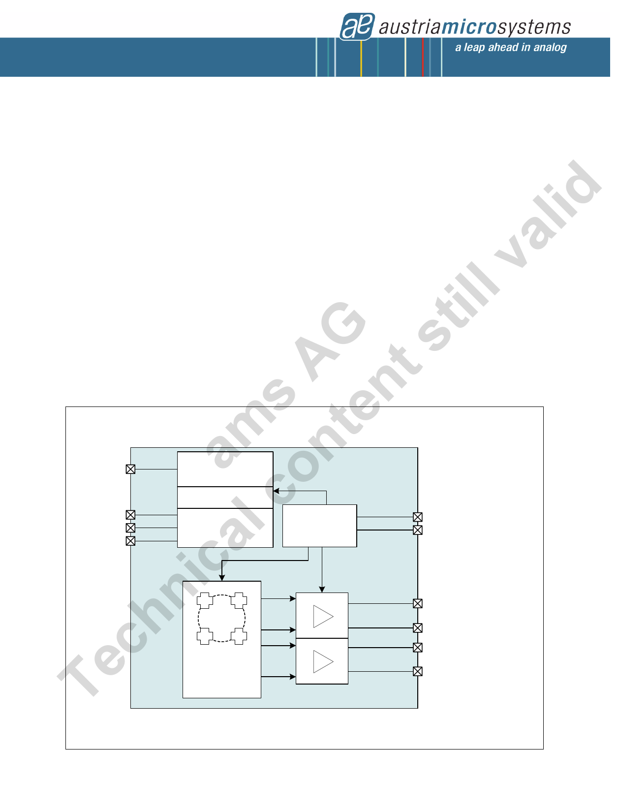
Figure 1. AS5115 Block Diagram
The AS5115 is ideal for several automotive and industrial
applications.
PROG
CS
DCLK
DIO
OTP Register
Digital Part
SSI Interface
AS5115
Power
Management
VDD
VSS
Hall Array
&
Frontend
Amplifier
Buffer Stage
Buffer Stage
SINP/SINN
SINN/SINP/CM_SIN
COSP/COSN
COSN/COSP/CM_COS
www.austriamicrosystems.com/AS5115
Revision 1.11
1 - 20
1 page 
AS5115
Datasheet - Electrical Characteristics
6 Electrical Characteristics
Unless otherwise noted in this specification, all defined tolerances of parameters are assured over the whole operation conditions range and also
over lifetime.
Table 3. Operating Conditions
Symbol
Parameter
Condition
Min Typ Max Unit
VDD Positive Supply Voltage
4.5 5.5 V
VSS Negative Supply Voltage
0.0 0.0 V
T_amb
Ambient temperature
-40 150 ºC
Table 4. DC/AC Characteristics for Digital Inputs and Outputs
Symbol
CMOS Input
Parameter
V_IH High level input voltage
V_IL Low level input voltage
I_LEAK
CMOS Output
Input Leakage Current
V_OH
High level output voltage
V_OL
Low level output voltage
C_L Capacitive Load
CMOS Output Tristate
I_OZ Tristate Leakage Current
Condition
4mA
4mA
Min Typ Max Unit
0.7 * VDD
0
VDD
0.3 * VDD
1
V
V
µA
VDD - 0.5
0
VDD
VSS + 0.4
35
V
V
pF
1 µA
Table 5. Magnetic Input Specification
Symbol
Parameter
BZpp Magnetic input field amplitude
B_offset
frot
Magnetic field offset
Rotational speed
Condition
Peak to peak at the radius
(=1mm) of the hall array
Within the linear range of the magnet
Maximum 30,000 RPM
Min Typ Max Unit
32 160 mT
-10 +10 mT
0 500 Hz
Table 6. Electrical System Specifications
Symbol
Parameter
Condition
IDD
Current Consumption
Maximum value derived at maximum I_H
(Hall Bias Current)
tpower_on
tprop
M
Power up time
Propagation delay
Magnetic Sensitivity
-40ºC to 150ºC
Version: AS5115
Version: AS5115A
VPP
Analog output voltage amplitude
(peak to peak)
AMTemp AM tracking accuracy over temperature
AM Sin / Cos Amplitude mismatch
-40ºC to 150ºC
25ºC
Voffset1
Voffset2
DCoffdrift
Output DC offset voltage
DC Offset Drift
At no input signal; programmable OTP
setting (see page 8)
-40ºC to 150ºC
Min
18
10
20.72
1.38
-1
-2
1.47
2.45
-50
Typ Max Unit
28 mA
1.275
ms
22 30 µs
60
mV / mT
28 35.28
1.94 2.5
V
+1 %
+2 %
1.5 1.53
2.5 2.55
V
+50 µV/ºC
www.austriamicrosystems.com/AS5115
Revision 1.11
5 - 20
5 Page 
AS5115
Datasheet - Detailed Description
7.6 Waveform – Digital Interface at Analog Readback of the Zener Diodes
To be sure that all Zener-Diodes are correctly burned, an analog readback mechanism is defined. Perform the ‘READ OTP ANA’ sequence
according to the command table and measure the value of the diode at the end of each phase.
Figure 7. Digital Interface at Analog Readback of Zener Diodes
CMD_PHASE
DCLK
CS
DIO
PROG
CMD4 CMD3 CMD2 CMD1 CMD0
OTP D45
EXT D45
DATA_PHASE_EXTENDED
EXT D44
EXT D1
OTP D44
OTP D43
perform analog measurements at PROG
OTP D0
EXT D0
Table 12. Serial Bit Sequence (16-bit read / write)
Write Command
Read / Write Data
C4 C3 C2 C1 C0 D15 D14 D13 D12 D11 D10 D9 D8 D7 D6 D5 D4 D3 D2 D1 D0
7.7 One Time Programming Content
The AS5115 die has an integrated 46-bit OTP ROM (Easyzapp) for trimming and configuration purposes. The PROM can be programmed via.
the serial interface. For irreversible programming, an external programming voltage at PROG pin is needed. For security reasons, the factory
trim bits can be locked by a lock bit.
As shown in the table below, the OTP holds 46 bits. Bit number 44 and 45 are used for OTP testing purposes and ESD protection of the
remaining cells.
Name
Hall_b
dc_offset
gain
Lock
invert_channel
cm_sin
cm_cos
Bit Count
6
1
2
1
OTP Start
0
6
7
13
OTP End
5
6
8
13
1 11 11
1 10 10
1 99
Access
user
user
user
austriamicrosystems
user
user
user
Comments
Sets overall sensitivity
Output DC offset setting
Output Buffer Gain setting
Set in production test
Inverts SIN and COS channel before the PGA for
inverted output function
Common mode voltage output enabled at SINN /
CM pin
Common mode voltage output enabled at COSN /
CM pin
Remark: OTP assignment will be defined/updated.
www.austriamicrosystems.com/AS5115
Revision 1.11
11 - 20
11 Page | ||
| Páginas | Total 20 Páginas | |
| PDF Descargar | [ Datasheet AS5115.PDF ] | |
Hoja de datos destacado
| Número de pieza | Descripción | Fabricantes |
| AS5115 | Programmable 360-o Magnetic Angle Encoder | austriamicrosystems AG |
| Número de pieza | Descripción | Fabricantes |
| SLA6805M | High Voltage 3 phase Motor Driver IC. |
Sanken |
| SDC1742 | 12- and 14-Bit Hybrid Synchro / Resolver-to-Digital Converters. |
Analog Devices |
|
DataSheet.es es una pagina web que funciona como un repositorio de manuales o hoja de datos de muchos de los productos más populares, |
| DataSheet.es | 2020 | Privacy Policy | Contacto | Buscar |