|
|
|
PDF AS1123 Data sheet ( Hoja de datos )
| Número de pieza | AS1123 | |
| Descripción | 16 -Channel LED Driver | |
| Fabricantes | austriamicrosystems AG | |
| Logotipo | ||
Hay una vista previa y un enlace de descarga de AS1123 (archivo pdf) en la parte inferior de esta página. Total 24 Páginas | ||
|
No Preview Available !
Datasheet
AS1123
Constant-Current, 16-Channel LED Driver with Diagnostics
1 General Description
The AS1123 is designed to drive up to 16 LEDs through a fast serial
interface and features 16 output constant current drivers and an on-
chip diagnostic read-back function.
The high clock-frequency (up to 50MHz), adjustable output current,
and flexible serial interface makes the device perfectly suited for
high-volume transmission applications.
Output current is adjustable (up to 40mA/channel) using an external
resistor (REXT).
The serial interface with Schmitt trigger inputs includes an integrated
shift register. Additionally, an internal data register stores the cur-
rently displayed data.
The device features integrated diagnostics for over-
temperature, open-LED, and shorted-LED conditions. Integrated
registers store global fault status information during load as well as
the detailed temperature/open-LED/shorted-LED diagnostics results.
The AS1123 also features a low-current diagnostic mode to minimize
display flicker during fault testing.
The AS1123 is available in a 24-pin QSOP and a 24-pin TQFN
(4x4mm) package.
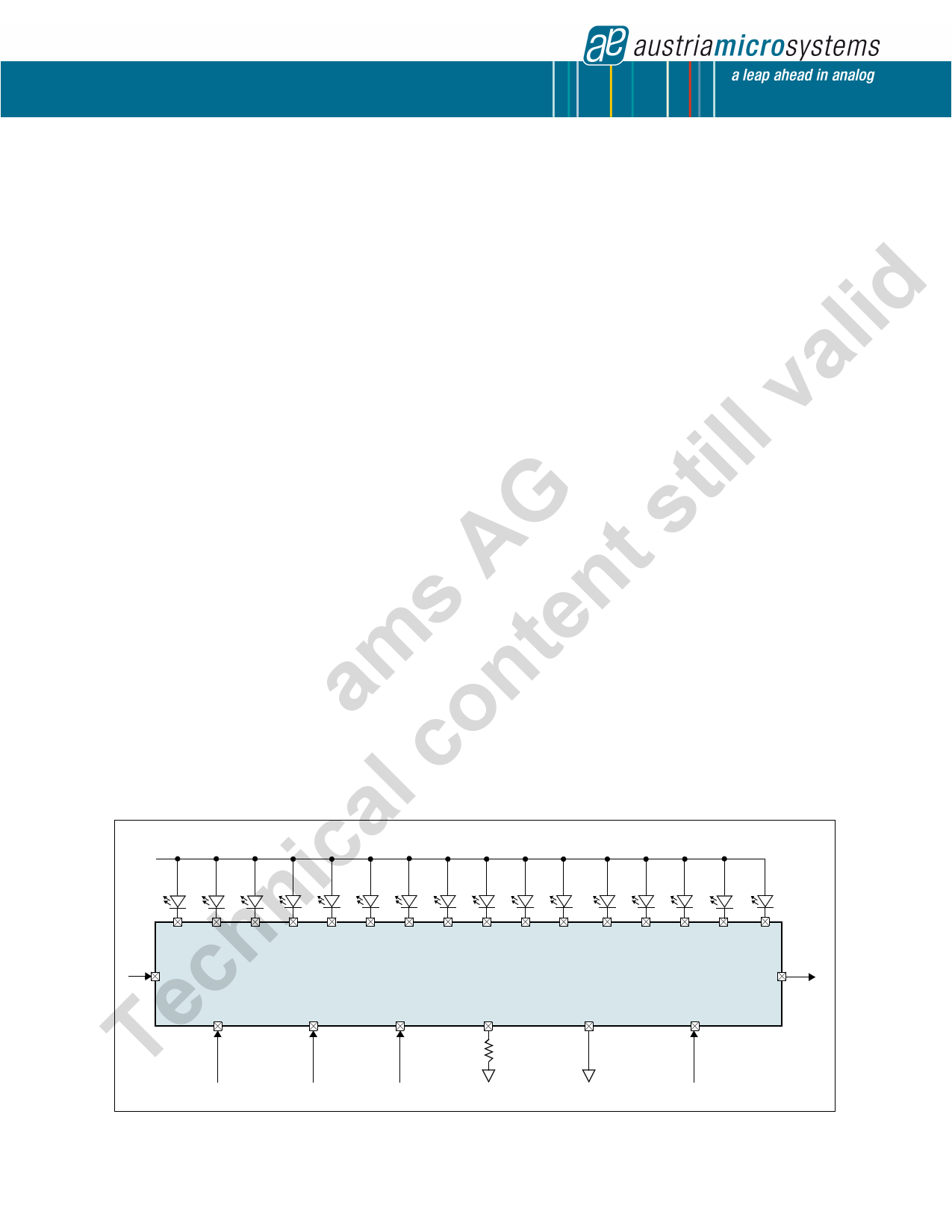
Figure 1. AS1123 - Typical Application Diagram
2 Key Features
16 Constant-Current Output Channels
Excellent Output Current Accuracy
- Between Channels: <±3%
- Between Devices: <±3%
Output Current Per Channel: 0.5mA to 40mA
Over-Temperature, Open-LED, Shorted-LED
Diagnostic Functions
Low-Current Test Mode
Global Fault Monitoring
Fast Serial Interface: 50MHz
Cascaded Configuration
Extremely Fast Output Drivers Suitable for PWM
Output Delay for controlling Inrush Current (on request)
24-pin QSOP and 24-pin TQFN (4x4mm) Package
3 Applications
The device is ideal for fixed- or slow-rolling displays using static or
multiplexed LED matrix and dimming functions, large LED matrix dis-
plays, mixed LED display and switch monitoring, displays in eleva-
tors, public transports (underground, trains, buses, taxis, airplanes,
etc.), large displays in stadiums and public areas, price indicators in
retail stores, promotional panels, bar-graph displays, industrial con-
troller displays, white good panels, emergency light indicators, and
traffic signs.
+VLED
AS1123
SDI
CLK
LD
OEN
REXT
GND
VDD
SDO
www.austriamicrosystems.com/LED-Driver-ICs
Revision 1.00
1 - 24
1 page 
AS1123
Datasheet - Electrical Characteristics
Switching Characteristics
VDD = 3.0 to 5.5V, VDS = 0.8V, VIH = VDD, VIL = GND, REXT = 940Ω, VLOAD = 4.0V, RLOAD = 64Ω, CLOAD = 10pF; The Switching Charac-
teristics are guaranteed by design.
Table 4. Switching Characteristics for VDD = 5V
Symbol
Parameter
Conditions
Min Typ Max Unit
tP1
tP2
Propagation Delay Time
(Without Staggered Output Delay)
tP3
CLK - SDO
LD - OUTNn
OEN - OUTNn
5 10 ns
250 500 ns
250 500
tP4 Propagation Delay Time
10 ns
tW(CLK)
CLK 15
tW(L)
Pulse Width
LD 15 ns
tW(OE)
OEN (@IOUT < 40mA)
500
tR * CLK Rise Time
500 ns
tF * CLK Fall Time
500 ns
tOR Output Rise Time of VOUT (Turn Off)
tbd 500 ns
tOF Output Fall Time of VOUT (Turn On)
tbd 500 ns
tSU(D)
Setup Time for SDI
5 ns
tH(D) Hold Time for SDI
5 ns
tSU(L)
Setup Time for LD
5 ns
tH(L) Hold Time for LD
5 ns
tTESTING
OEN Time for Error Detection
2000 ns
tSTAG
Staggered Output Delay
(only for AS1123B)
20 40 ns
tSU(OE)
Output Enable Setup Time
20 ns
tGSW(ERROR) Global Error Switching Setup Time
10 ns
tSU(ERROR) Global Error Detection Setup Time
10 ns
tP(I/O)
Propagation Delay Global Error Flag
5 ns
tSW(ERROR) Switching Time Global Error Flag
10 ns
fCLK Clock Frequency (Cascade Operation)
30 MHz
tP3,ON
tP3,OFF
tREXT2,1
tREXT2,1
Low-Current Test Mode
Propagation Delay Time
External Resistor Reaction Time
External Resistor Reaction Time
Turn ON
Turn OFF
Change from REXT1 = 470Ω, IOUT1 = 40mA to
REXT2 = 4.7kΩ, IOUT2 = 4mA
Change from REXT1 = 4.7kΩ, IOUT1 = 4mA to
REXT2 = 470Ω, IOUT2 = 40mA
3 5 µs
0.05 0.1 µs
0.5 1 µs
0.5 1 µs
* If multiple AS1123 devices are cascaded and tr or tf is large, it may be critical to achieve the timing required for data transfer between two cas-
caded LED drivers.
www.austriamicrosystems.com/LED-Driver-ICs
Revision 1.00
5 - 24
5 Page 
AS1123
Datasheet - Detailed Description
Error Detection Functions
Open-LED Detection
The AS1123 open-LED detection is based on the comparison between VDS and VTHL. The open LED status is aquired at the rising edge of
OEN and stored internally. While detecting open-LEDs the output port must be turned on. Open LED detection can be started with 1 clock pulse
during error detection mode while the output port is turned on.
Note: LEDs which are turned off at test time cannot be tested and will be shown as a logic 1 in the detailed error report.
Table 6. Open LED Detection Modes
Output Port State
On
On
Effective Output
Point Conditions
VDS < VTHL
VDS > VTHL
Detected Open-LED
Error Status Code
0
1
Meaning
Open Circuit
Normal
Shorted-LED
The AS1123 shorted-LED detection is based on the comparison between VDS and VTHH. The shortened LED status is acquired at the rising
edge of OEN and stored internally. While detecting shorted-LEDs the output port must be turned on. Shorted-LED detection can be started with
2 clock pulses during error detection mode while the output port is turned on.
For valid results, the voltage at OUTN0:OUTN15 must be lower then VTHH under low-current diagnostic mode operating conditions. This can be
achieved by reducing the VLED voltage or by adding additional diodes, resistors or LED’s.
Note: LEDs which are turned off at test time cannot be tested and will be shown as a logic 1 in the detailed error report.
Table 7. Shorted LED Detection Modes
Output Port State
On
On
Effective Output
Point Conditions
VDS > VTHH
VDS < VTHH
Detected Shorted-LED
Error Status Code
0
1
Meaning
Short Circuit
Normal
Overtemperature
Thermal protection for the AS1123 is provided by continuously monitoring the device’s core temperature. The overtemperature status is acquired
at the rising edge of OEN and stored internally.
Table 8. Overtemperature Modes
Output Port State
Don’t Care
Don’t Care
Effective Output
Point Conditions
Temperature > TOV1
Temperature < TOV1
Detected Overtemperature
Status Code
0
1
Meaning
Overtemperature Condition
Normal
www.austriamicrosystems.com/LED-Driver-ICs
Revision 1.00
11 - 24
11 Page | ||
| Páginas | Total 24 Páginas | |
| PDF Descargar | [ Datasheet AS1123.PDF ] | |
Hoja de datos destacado
| Número de pieza | Descripción | Fabricantes |
| AS1120 | 46-Segment LCD Driver | austriamicrosystems AG |
| AS1120 | 12 Channels Capacitive Touch Sensor IC | ASI |
| AS1121 | 16-Channel LED Driver | austriamicrosystems AG |
| AS1122 | 12-Channel LED Driver | austriamicrosystems AG |
| Número de pieza | Descripción | Fabricantes |
| SLA6805M | High Voltage 3 phase Motor Driver IC. |
Sanken |
| SDC1742 | 12- and 14-Bit Hybrid Synchro / Resolver-to-Digital Converters. |
Analog Devices |
|
DataSheet.es es una pagina web que funciona como un repositorio de manuales o hoja de datos de muchos de los productos más populares, |
| DataSheet.es | 2020 | Privacy Policy | Contacto | Buscar |