|
|
|
PDF AS1110 Data sheet ( Hoja de datos )
| Número de pieza | AS1110 | |
| Descripción | 16-Channel LED Driver | |
| Fabricantes | ams | |
| Logotipo | ||
Hay una vista previa y un enlace de descarga de AS1110 (archivo pdf) en la parte inferior de esta página. Total 24 Páginas | ||
|
No Preview Available !
AS1110
Constant-Current, 16-Channel LED Driver with Diagnostics
1 General Description
The AS1110 is designed to drive up to 16 LEDs through a fast serial
interface and features 16 output constant current drivers and an on-
chip diagnostic read-back function.
The high clock-frequency (up to 50MHz), adjustable output current,
and flexible serial interface makes the device perfectly suited for
high-volume transmission applications.
Output current is adjustable (up to 100mA/channel) using an external
resistor (REXT).
The serial interface with Schmitt trigger inputs includes an integrated
shift register. Additionally, an internal data register stores the
currently displayed data.
The device features integrated diagnostics for over-
temperature, open-LED, and shorted-LED conditions. Integrated
registers store global fault status information during load as well as
the detailed temperature/open-LED/shorted-LED diagnostics results.
The AS1110 also features a low-current diagnostic mode to minimize
display flicker during fault testing.
The AS1110 is available in a 24-pin SSOP and the 28-pin QFN
(5x5mm) package.
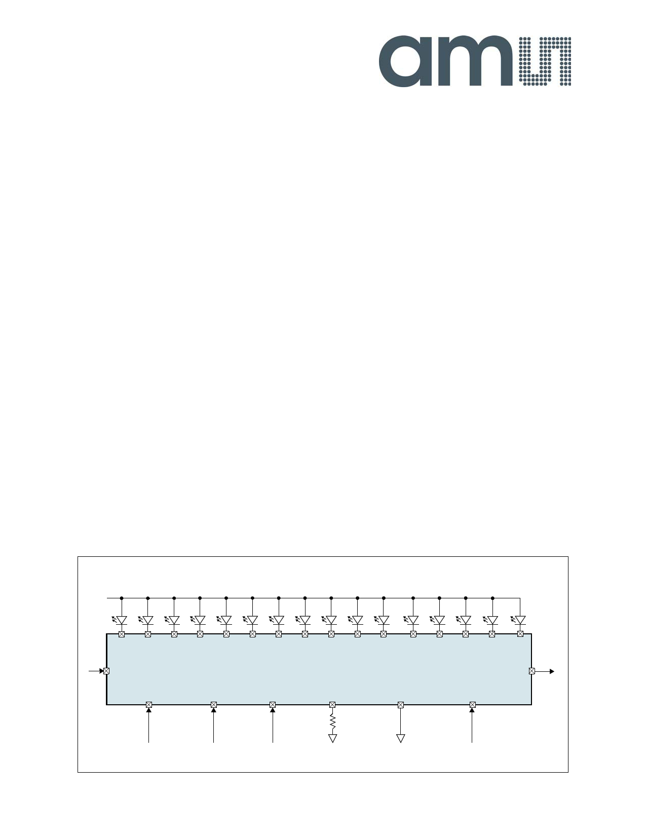
Figure 1. Main Diagram and Pin Assignments
2 Key Features
16 Constant-current output channels
Excellent output current accuracy
- Between channels: <±3%
- Between devices: <±3%
Output current per channel: 0.5mA to 100mA
Controlled In-rush current
Over-Temperature, Open-LED, Shorted-LED
Diagnostic functions
Low-current test mode
Global fault monitoring
Low shutdown mode current: 10µA
Fast serial interface: 50MHz
Cascaded configuration
Extremely fast output drivers suitable for PWM
24-pin SSOP and 28-pin QFN (5x5mm) Package
3 Applications
The device is ideal for fixed- or slow-rolling displays using static or
multiplexed LED matrix and dimming functions, large LED matrix
displays, mixed LED display and switch monitoring, displays in
elevators, public transports (underground, trains, buses, taxis,
airplanes, etc.), large displays in stadiums and public areas, price
indicators in retail stores, promotional panels, bar-graph displays,
industrial controller displays, white good panels, emergency light
indicators, and traffic signs.
+VLED
SDI
CLK
AS1110
LD OEN REXT
GND
SDO
VDD
www.ams.com/LED-Driver-ICs/AS1110
Revision 1.6
1 - 24
1 page 
AS1110
Datasheet - Electrical Characteristics
Table 3. Electrical Characteristics (Continued)
Symbol
IDD(OFF)0
IDD(OFF)1
IDD(OFF)2
IDD(OFF)3
IDD(ON)1
IDD(ON)2
IDD(ON)3
Parameter
Supply Current
OFF
ON
Condition
REXT = Open‚ OUTN0:15 = Off
REXT = 744Ω‚ OUTN0:15 = Off
REXT = 372Ω‚ OUTN0:15 = Off
REXT = 186Ω, OUTN0:15 = Off
REXT = 744Ω‚ OUTN0:15 = On
REXT = 372Ω‚ OUTN0:15 = On
REXT = 186Ω‚ OUTN0:15 = On
Min Typ Max Unit
2.7 6
4.3 8
5.4 9
9.3 13 mA
6.2 11
10.5 15
19.5 26
6.1 Switching Characteristics
VDD = 3.0 to 5.5V, VDS = 0.8V, VIH = VDD, VIL = GND, REXT = 372Ω, VLOAD = 4.0V, RLOAD = 64Ω, CLOAD = 10pF; guaranteed by design.
Table 4. Switching Characteristics for VDD = 5V
Symbol
Parameter
Conditions
Min Typ Max Unit
tP1
tP2
Propagation Delay Time
(Without Staggered Output Delay)
tP3
CLK - SDO
LD - OUTNn
OEN - OUTNn
5 10
100 200
100 200
ns
tP4 Propagation Delay Time
10 ns
tW(CLK)
CLK 15
tW(L)
Pulse Width
LD 15
ns
tW(OE)
OEN (@IOUT < 60mA)
200
tR * CLK Rise Time
500 ns
tF * CLK Fall Time
500 ns
tOR Output Rise Time of VOUT (Turn Off)
100 200 ns
tOF Output Fall Time of VOUT (Turn On)
100 300 ns
tSU(D)
Setup Time for SDI
5 ns
tH(D) Hold Time for SDI
5 ns
tSU(L)
Setup Time for LD
5 ns
tH(L) Hold Time for LD
5 ns
tTESTING
OEN Time for Error Detection
2000 ns
tSTAG
Staggered Output Delay
20 40 ns
tSU(OE)
Output Enable Setup Time
20 ns
tGSW(ERROR)
Global Error Switching Setup Time
10 ns
tSU(ERROR)
Global Error Detection Setup Time
10 ns
tP(I/O)
Propagation Delay Global Error Flag
5 ns
tSW(ERROR)
Switching Time Global Error Flag
10 ns
fCLK
Maximum Clock Frequency
(Cascade Operation)
30 50
MHz
tP3,ON
tP3,OFF
Low-Current Test Mode
Propagation Delay Time
Turn ON
Turn OFF
35
0.05 0.1
µs
µs
www.ams.com/LED-Driver-ICs/AS1110
Revision 1.6
5 - 24
5 Page 
AS1110
Datasheet - Detailed Description
Figure 13. Switching Global Error Mode Timing Diagram
OEN
LD
tTESTING
tGSW(ERROR)
tSU(ERROR)
tP(I/O)
CLK tGSW(ERROR)
tP(I/O)
tGSW(ERROR)
tP(I/O)
SDI
TFLAG(IN)
OFLAG(IN)
SFLAG(IN)
SDO
Don’t
Care
TFLAG
Don’t
Care
OFLAG
Don’t
Care
SFLAG
Acquisition of Error
Status
tP4
tSW(ERROR)
tSW(ERROR)
8.3 Error-Detection Mode
Acquisition of the error status occurs at the rising edge of OEN. Error-detection mode is started on the rising edge of LD when OEN is high. The
CLK signal must be low when entering error detection mode. Error detection for open- and shorted-LEDs can only be performed for LEDs that
are switched on during test time. To switch between error-detection modes clock pulses are needed (see Table 5).
Note: To test all LEDs, a test pattern that turns on all LEDs must be input to the AS1110.
8.4 Global Error Mode
Global error mode is entered when error-detection mode is started. Clock pulses during this period are used to select between temperature,
open-LED, and shorted-LED tests, as well as low-current diagnostic mode and shutdown mode (see Table 5). In global error mode, an error flag
(TFLAG, OFLAG, SFLAG) is delivered to pin SDO if any errors are encountered.
Table 5. Global Error Mode Selections
Clock
Pulses
0
1
2
3
4
Output Port
Don't Care
Enabled
Enabled
Don't Care
Don't Care
Error-Detection Mode
Global Error Flag/Shutdown Condition
Over-Temperature Detection
Open-LED Detection
Shorted-LED Detection
Low-Current Diagnostic Mode
Shutdown Mode
TFLAG = SDO = 1: No over-temperature warning.
TFLAG = SDO = 0: Over-temperature warning.
OFLAG = SDO = 1: No open-LED error.
OFLAG = SDO = 0: Open-LED error.
SFLAG = SDO = 1: No shorted-LED error.
SFLAG = SDO = 0: Shorted-LED error.
SDI = 1: Wakeup
SDI = 0: Shutdown
Note: For a valid result SDI must be 1 for the first device.
If there are multiple AS1110s in a chain, the error flag will be gated through all devices. To get a valid result at the end of the chain, a logic 1 must
be applied to the SDI input of the first device of the chain. If one device produces an error this error will show up after n*tP(I/O) + tSW(ERROR) at
pin SDO of the last device in the chain. This means it is not possible to identify which device in the chain produced the error. Therefore, if a global
error occurs, the detailed error report can be run to identify which AS1110, or LED produced the error.
Note: When no error has occurred, the detailed error report can be skipped, setting LD and subsequently OEN low.
www.ams.com/LED-Driver-ICs/AS1110
Revision 1.6
11 - 24
11 Page | ||
| Páginas | Total 24 Páginas | |
| PDF Descargar | [ Datasheet AS1110.PDF ] | |
Hoja de datos destacado
| Número de pieza | Descripción | Fabricantes |
| AS111 | Voltage Comparator | Micross |
| AS111 | Voltage Comparator | Austin Semiconductor |
| AS1110 | 16-Channel LED Driver | austriamicrosystems AG |
| AS1110 | 16-Channel LED Driver | ams |
| Número de pieza | Descripción | Fabricantes |
| SLA6805M | High Voltage 3 phase Motor Driver IC. |
Sanken |
| SDC1742 | 12- and 14-Bit Hybrid Synchro / Resolver-to-Digital Converters. |
Analog Devices |
|
DataSheet.es es una pagina web que funciona como un repositorio de manuales o hoja de datos de muchos de los productos más populares, |
| DataSheet.es | 2020 | Privacy Policy | Contacto | Buscar |