|
|
|
PDF AS2533-36 Data sheet ( Hoja de datos )
| Número de pieza | AS2533-36 | |
| Descripción | Multi-Standard CMOS Telephone IC | |
| Fabricantes | austriamicrosystems AG | |
| Logotipo | ||
Hay una vista previa y un enlace de descarga de AS2533-36 (archivo pdf) en la parte inferior de esta página. Total 25 Páginas | ||
|
No Preview Available !
Multi-Standard CMOS Telephone IC
for Basic Telephones
AS2533-36
General Description
The AS253x is a CMOS integrated circuit that contains all
the functions needed to build a high performance electronic
telephone set with basic features.
The AS253x incorporates a line interface, a speech circuit,
a dialler and ringer. It is a real single-chip / single-die IC
with 28 pins. It allows either package mounting or chip-on-
board mounting.
The device is available in 4 versions (pin-compatible) with
different features ranging from LNR only (last number
redial) to 4 direct (one-touch) memories and 10 indirect
(two-touch) memories. The sliding cursor procedure makes
the LNR function easy to use under various PABX systems.
The versatility of the circuit is provided by pin options and a
few external components. This allows fast time-to-market
and easy adaptation to different PTT requirements. A
unique EMI performance has been achieved due to the
consequent use of CMOS amplifiers.
Key Features
Line Interface and Speech Circuit
- Electronic Rx volume control
- Electronic microphone mute
- Microphone amplifier with symmetrical input
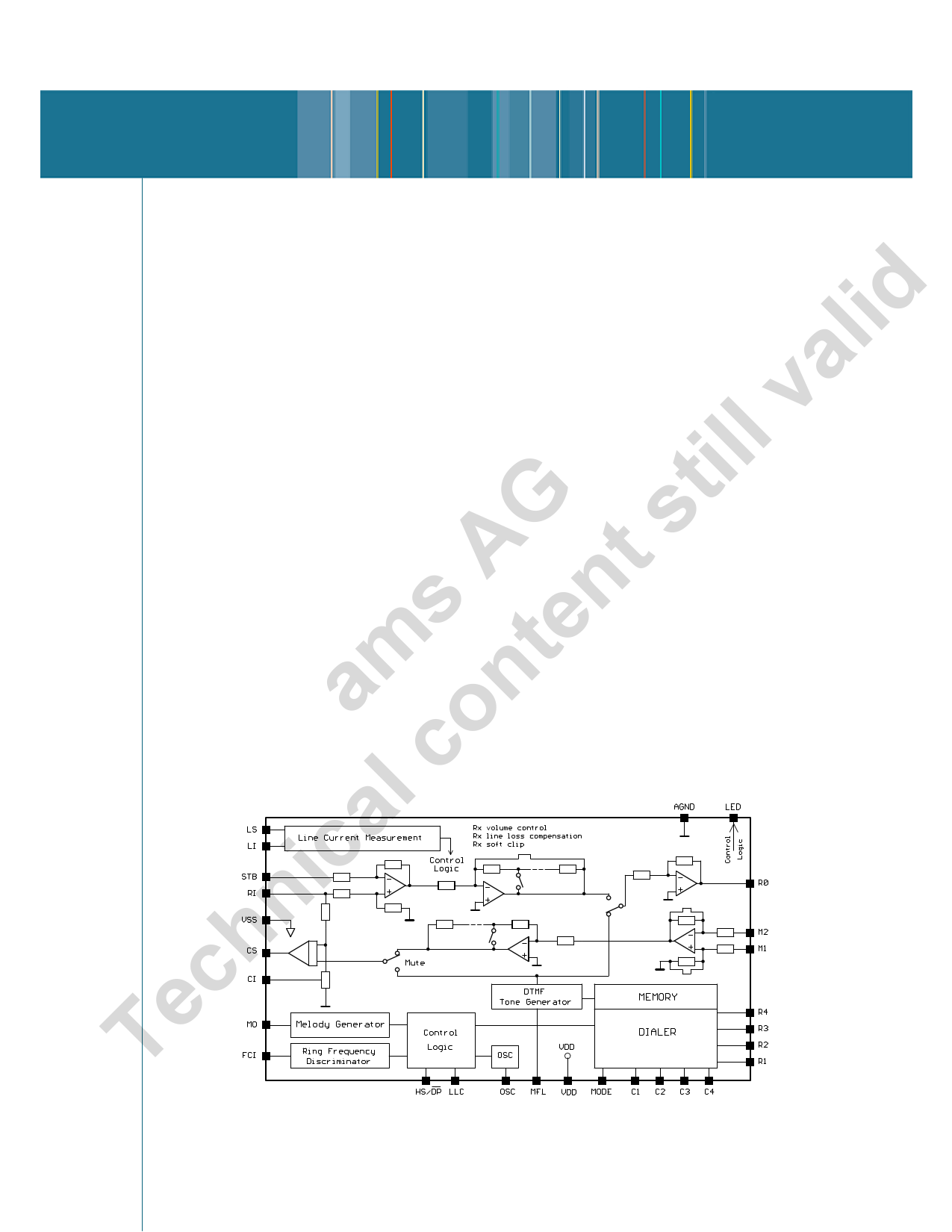
Block Diagram
austriamicrosystems
DATA SHEET
- Rx and Tx soft clipping to avoid harsh distortion
- Real or complex impedance (EU compliant)
- Stabilized supply for dialler and peripherals
- Automatic line loss compensation
- Operating range from 13 to 100 mA (down to 5 mA with
reduced performance)
- Unique EMI performance (EU compliant)
Dialler
- LD/MF dialing and mixed-mode dialing
- 31 digit last number redial (LNR)
- 4 direct/10 indirect (AS2533/36), 12 direct (AS2535)
- Repeat dialing by busy or engaged (not AS2535)
- Confidence tone during memory programming and mute
- Notepad memory function
- Pause key for access pause or wait function
- 3 flash timings, 100 ms, 280 ms and 375/600 ms
- Sliding cursor protocol with comparison
Ringer
- Ring frequency discrimination
- 3-tone melody generator
- Ring melody selection via keyboard
- Ring volume selection via keyboard
- Version available with fixed ring melody and ring volume
Package
- SOIC 28 or DIE
Revision 8.10
Figure 1 Block Diagram
Page 1 of 25
1 page 
Data Sheet AS2533-36
austriamicrosystems
Keyboard Connections continued
(either VOL or +/– keys)
C1 C2 C3 C4
R1
PP // MM
11
22
33
R2 44 55 66 77
R3 88 99 00 **
R4 ## RR 11 RR 22 RR 33
LLNNRR VVOOLL
++
−−
MM 11 MM 22 MM 33 MM 44
MM 55 MM 66 MM 77 MM 88
MM 99
MM 1100
MM 1111
MM 1122
Figure 4 Keyboard Connection AS2535
Power On Reset
The on chip power on reset circuit monitors the supply
voltage (VDD ) during off-hook. When VDD rises above
approx. 1.2V, a power on reset occurs which clears the
RAM.
DC Conditions
The normal operating range is from 13 mA to 100 mA.
Operating range with reduced performance is from 5 mA to
13 mA (parallel operation). In the operating range all
functions are operational.
At line currents below 13 mA the AS253x provides an
additional slope below 4.5V in order to allow parallel
operation (see Figure 12).
The dc characteristic (excluding diode bridge) is
determined by the voltage at LI and the resistor R1 at line
currents above 13 mA as follows:
VLS = VLI + ILINE × R1
The voltage at LI is 4.5V in the normal operating range.
During pulse dialing the speech circuit and other part of
the device not operating is in a power down mode to save
current. The CS pin is pulled to VSS in order to turn the
external shunt transistor on to keep a low voltage drop at
the LS pin during make periods.
AC Impedance
The ac impedance of the circuit is set by external
components. The impedance can be real or complex.
The ac impedance is determined as follows:
ZAC = 33 Z1
The dc value of Z1 should be 30 Ω to maintain correct dc
performance.
Return loss and side tone cancellation can be determined
independent of each other.
Speech Circuit
The speech circuit consists of a transmit and a receive
path with dual soft clipping, mute, line loss compensation
and sidetone cancellation.
Revision 8.10
Page 5 of 25
5 Page 
Data Sheet AS2533-36
austriamicrosystems
Programming Procedures
Procedure Principles
The procedures for utilizing the features of the AS253x are
optimized out of consideration for the human factor in
order to:
- meet the user’s expectations
- be easy to learn and relearn
- not invoke any automatic functions which the user
doesn’t expect
- protect the user from committing critical errors, e.g.
dialing wrong numbers, deleting stored numbers, etc.
- be consistent, simple and usable.
The following chapters describe the operating procedures
for the provided features. Pressing an invalid key or key
combination during programming will cause the device to
abort the program state. Pressing any key combination or
sequence which is not described or defined may cause the
device to enter a state or mode that does not comply with
the expectation of the user. In such cases, any undesired
state can be terminated at any time by going on-hook / off-
hook which will generate a functional reset.
Storing Numbers (not AS2534)
Up to 14 numbers, each with maximum 21 digits, can be
stored into the internal RAM.
1. Press [P/M] to enter program mode
2. Enter location (MR + digit1; or M1 to M12)
3. Enter number - entries (0-9, *, #, PS or LNR, R1, R2,
R3) will b written directly into the selected memory
location)
4. Press [P/M] to store and exit or go on-hook to abort
5. Go to 1 for storing further numbers
Programming Tone Ringer
Three different ringer melodies with three levels each can
be programmed. AS2534R cannot be programmed.
1. Press [P/M] to enter program mode
2. Press [#] for ringer programming mode
3. Enter Code to select ringer melody and volume(see
code table in section Tone Ringer (Melody/Volume)
4. Press [P/M] to store and exit or go on-hook to abort
1 Digit includes 0 – 9
When Code 0 (tone ringer off) has been programmed, the
device will automatically return to previous setting
(different from 0) by next off-hook.
Temporary MF
The procedure below assumes that the device is operated
in puls mode.
1. Go off-hook
2. Press [*] or [T/P] to switch to DTMF mode
3. Press [R] or [T/P] to switch back to PULS mode
4. Got to 2. to switch again to DTMF mode
Mode pin is connected to row 1, 2, 3, 4, or 5. When mode
pin = row 5, pressing the [*] key also transmits the tone by
MF selected. The [T/P] key (not AS2535) can be used
alternatively to the [*] key.
Automatic Dialing
The following procedure describes the dialing procedure
and the internal sequences:
1. Go off-hook
2. Enter the number by pressing digit, [M1]-[M12], [LNR]
or [MR] + digit
3. The number is internally buffed in the FIFO
4. Tone- or Puls-Dialing starts
5. Wait for connection
6. Got to 2 for entering postdialed digits
Postdialed digits are not stored but buffed in the FIFO.
Revision 8.10
Page 11 of 25
11 Page | ||
| Páginas | Total 25 Páginas | |
| PDF Descargar | [ Datasheet AS2533-36.PDF ] | |
Hoja de datos destacado
| Número de pieza | Descripción | Fabricantes |
| AS2533-36 | Multi-Standard CMOS Telephone IC | austriamicrosystems AG |
| Número de pieza | Descripción | Fabricantes |
| SLA6805M | High Voltage 3 phase Motor Driver IC. |
Sanken |
| SDC1742 | 12- and 14-Bit Hybrid Synchro / Resolver-to-Digital Converters. |
Analog Devices |
|
DataSheet.es es una pagina web que funciona como un repositorio de manuales o hoja de datos de muchos de los productos más populares, |
| DataSheet.es | 2020 | Privacy Policy | Contacto | Buscar |