|
|
|
PDF AGPS-L001 Data sheet ( Hoja de datos )
| Número de pieza | AGPS-L001 | |
| Descripción | GNSS Low Noise amplifier | |
| Fabricantes | AVAGO | |
| Logotipo | ||
Hay una vista previa y un enlace de descarga de AGPS-L001 (archivo pdf) en la parte inferior de esta página. Total 20 Páginas | ||
|
No Preview Available !
AGPS-L001
GNSS Low Noise amplifier with Variable bias current
and shutdown function
Data Sheet
Description
Avago Technologies’ AGPS-L001 is an ultra low-noise am-
plifier designed for GNSS band (GPS, GLONASS, Galileo
and Compass) applications. The LNA uses Avago Tech-
nologies’ proprietary GaAs Enhancement-mode pHEMT
process to achieve high gain with very low noise figures
and high linearity. Noise figure distribution is very tightly
controlled. Gain and supply current are guaranteed pa-
rameters. A CMOS compatible shutdown pin is included
to turn the LNA off and provide variable bias.
The LNA is usable down to 1.8V operation. It achieves low
noise figures and high gain even at 1.8V, making it suit-
able for use in critical low power GNSS band applications.
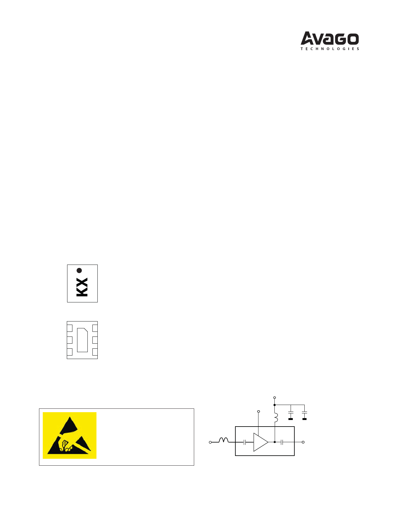
Component Image
Surface Mount (0.9 x 1.1 x 0.5) mm3 6-lead DFN
GnD (pin 1)
NC [1] (pin 2)
RFin (pin 3)
TOP VIEW
Vdd (pin 6)
Vsd (pin 5)
RFOut (pin 4)
Vdd (pin 6)
Vsd (pin 5)
RFOut (pin 4)
GnD
(pin 7)
GnD (pin 1)
NC [1] (pin 2)
RFin (pin 3)
BOTTOM VIEW
Note:
1. Pin 2 must be left unconnected.
2. Package marking provides orientation and identification
“K” = Product code
“X” = Month and year of manufacture
Attention: Observe precautions for han-
dling electrostatic sensitive devices.
ESD Machine Model = 70 V
ESD Human Body Model = 300 V
Refer to Avago Application Note A004R:
Electrostatic Discharge, Damage and Control.
Features
• Advanced GaAs E-pHEMT
• Low Noise Figure: 0.66dB typ.
• High Gain: 17.1dB typ.
• Low external component count
• High IIP3 and IP1dB
• Wide Supply Voltage: 1V to 3.6V
• Shutdown current : < 1uA
• CMOS compatible shutdown pin (Vsd)
• Adjustable bias current via single external resistor/
voltage
• Small Footprint: (0.9 x 1.1) mm2
• Low Profile: 0.5mm typ.
• Meets MSL1, Lead-free and halogen free
Specifications (Typical performance @ 25°C)
At 1.575GHz, Vdd = 2.7V, Idd = 6mA
• Gain = 17.1dB
• NF = 0.66dB
• IIP3 = 2.5dBm
• IP1dB = -4dBm
• S11 = -7.6dB, S22 =-17dB
Application
LNA for GNSS frequency bands
Application Circuit
Vdd = +2.7V
Vsd
C2 C3
RFin RFout
1 page 
AGPS-L001
GnD 1
NC [1] 2
L1
RFIn
3
Vdd
C3
R2 L4 Vsd
C2
L3 C1
R1
6
5
4 RFOut
Figure 2. Application Circuit
Notes
1. Pin 2 must be left unconnected.
2. L1 form the input matching network. The LNA module has integrated coupling and DC-block capacitors at the input and output respectively. Best
noise performance is obtained using high-Q wirewound inductors. This circuit demonstrates that low noise figures are obtainable with standard
0402 chip inductors.
3. L3 serves as an output matching inductor and supply choke.
4. C1, C2 and C3 are RF bypass capacitors. C1 is optional.
5. R2 and L4 is a network that isolates the measurement demoboard from external disturbances.
6. Bias control is achieved by either varying the VSD voltage without R1 (R1=0 ohm) or fixing the VSD voltage to Vdd and varying R1. Typical value for
R1 is 12kOhm for 6mA total current at Vsd=Vdd=+2.7V.
7. Higher gain and IP3 performance can be obtained by increasing the supply current. This can be achieved by reducing the value for R1 to obtain
desired current.
8. For low voltage operation such as 1.0V, the R1 may be omitted and Vsd connected directly to the supply pins.
5
5 Page 
1.6
-40°C
1.4 25°C
85°C
1.2
1
0.8
0.6
0.4
3 4 5 Id6d (mA) 7 8 9 10
Figure 24. [email protected] vs. Idd
1.6
-40°C
1.4 25°C
85°C
1.2
1
0.8
0.6
0.4
3 4 5 6 7 8 9 10
Idd (mA)
Figure 25. [email protected] vs. Idd
Figure 26. Edwards-Sinsky Output Stability Factor (Mu)
Figure 27. Edwards-Sinsky Input Stability Factor (Mu’)
20
0
-20
-40
-60
-80
-100
Idd = 4mA
Idd = 6mA
-120
-70 -60 -50 -40 -30 -20 -10 0
787.76 MHz input power level (dBm)
10
Figure 28. 2nd harmonics (1.57552GHz) vs 787.76MHz input signal power level
11
11 Page | ||
| Páginas | Total 20 Páginas | |
| PDF Descargar | [ Datasheet AGPS-L001.PDF ] | |
Hoja de datos destacado
| Número de pieza | Descripción | Fabricantes |
| AGPS-L001 | GNSS Low Noise amplifier | AVAGO |
| Número de pieza | Descripción | Fabricantes |
| SLA6805M | High Voltage 3 phase Motor Driver IC. |
Sanken |
| SDC1742 | 12- and 14-Bit Hybrid Synchro / Resolver-to-Digital Converters. |
Analog Devices |
|
DataSheet.es es una pagina web que funciona como un repositorio de manuales o hoja de datos de muchos de los productos más populares, |
| DataSheet.es | 2020 | Privacy Policy | Contacto | Buscar |