|
|
|
PDF AN75 Data sheet ( Hoja de datos )
| Número de pieza | AN75 | |
| Descripción | High Power Factor LED Replacement T8 Fluorescent Tube using the AL9910 High Voltage LED Controller | |
| Fabricantes | Diodes | |
| Logotipo | ||
Hay una vista previa y un enlace de descarga de AN75 (archivo pdf) en la parte inferior de esta página. Total 12 Páginas | ||
|
No Preview Available !
AN75
AN75
High Power Factor LED Replacement T8 Fluorescent Tube
using the AL9910 High Voltage LED Controller
Yong Ang, Diodes Inc.
Introduction
This application note describes the principles and design equations required for the design of a high
brightness LED lamp using the AL9910. The equations are then used to demonstrate the design of a
universal, offline, high power factor (PF), 13W LED lamp suitable for use as the replacement for T8
fluorescent tube. A complete design including the electrical diagram, component list and performance
measurements are provided.
AL9910 high power factor buck LED driver
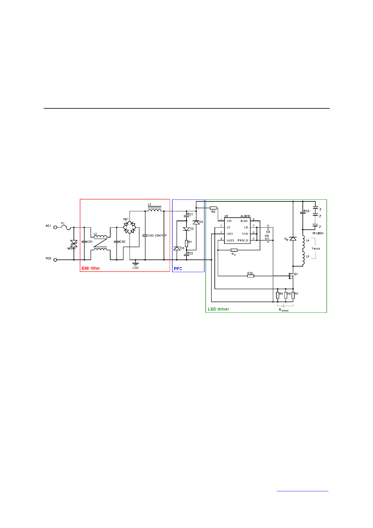
Figure 1 Electrical schematic of a high power factor 13W LED lamp
Figure 1 shows the electrical diagram of an offline 13W LED driver.
On the input side, CX1, CX2, CX3, CX4, L1 and L2 provide sufficient filtering for both differential mode
and common mode EMI noise which are generated by the switching converter circuit.
The rectified AC line voltage from the bridge rectifier DB1 is then fed into a passive power factor
correction or valley fill circuit which consists of 3 diodes and 2 capacitors. D1, D2, D3, C1, C2 improve
the input line current distortion in order to achieve PF greater than 0.9 for the AC line input.
The constant current regulator section consists of a buck converter driven by the AL9910. Normally,
the buck regulator is used in fixed frequency mode but its duty cycle limitation of 50% is not practical
for offline lamp. This problem can be overcome by changing the control method to a fixed off-time
operation.
The design of the internal oscillator in the AL9910 allows the IC to be configured for either fixed
frequency or fixed off-time based on how resistor RT is connected. For fixed off-time operation, the
resistor RT is connected between the Gate and ROSC pins, as shown in Figure 1. This converter has
now a constant off-time when the power MOSFET is turned off. The on-time is based on the current
Issue 1 – January 2011
© Diodes Incorporated 2010
1
www.diodes.com
1 page 
AN75
Maximum drain-source voltage stress on the power MOSFET for this converter is equal to the input
voltage. However, a typical voltage safety margin for the MOSFET defines the maximum reverse
voltage as follows,
VDSS = 1.3 × VIN(max) = 1.3 × 373V = 485V
which implies that a common 500V MOSFET is suitable.
The power MOSFET losses will be dominated by switching loss. The switching loss depends on the
switching time, frequency, MOSFET drain current and drain-source voltage. The switching rise time
tRISE and fall time tFALL is a function of the MOSFET’s gate capacitance, the gate driver capability of the
AL9910 and layout design. The worse case switching power losses occurs at VLED(min) and VIN(max).
The switching loss is approximately,
PSW
=
VIN(max) × ⎜⎜⎝⎛Ipk
−
VLED(min)tOFF
LBUCK
2
⎟⎟⎠⎞ × tRISE × fswi(max)
+
VIN(max) × Ipk
× tFALL × fswi(max)
2
=
373V
×
(297mA
−
88mA
2
)×
65ns
×
63.8kHz
+
373V
×
65ns
2
×
63.8kHz
= 455mW
where the switching time tRISE and tFALL are measured to be 65ns with the 600V MOSFET
SPB03N60S5 as the power MOSFET. As shown in Figure 1, R10 is a series gate resistor that slows
down the MOSFET switching and reduces EMI emission.
The RMS current through the MOSFET at VLED(min) and VIN(max) is given by,
ID(RMS) =
VLED(min)
VIN(max)
× ⎜⎜⎝⎛ILED(nom)
+
VLED(min)
× tOFF
12
LBUCK ⎟⎟⎠⎞
=
42V
373V
× ⎜⎜⎝⎛240mA
+
42V
× 13.9μs
12
6.6mH
⎟⎟⎠⎞
= 89mA
The power MOSFET conduction loss depends on its static drain-source resistance RDS(ON) at the
MOSFET working temperature. It is possible to calculate the continuous conduction loss:
( )PCOND = ID2(RMS) × RDS(ON) = 89mA 2 × 2.5Ω = 19mW
The total power MOSFET loss is:
PTOT = PSW + PCOND = 455mW + 19mW = 474mW
Total MOSFET power loss is dissipated from the SMD package into the PC Board. So it is possible to
calculate the MOSFET working junction temperature can be calculated if the package junction-to-
ambient thermal resistance RthJA is known. The calculated MOSFET junction temperature, TJ, must be
lower then the maximum allowable junction temperature TJ(MAX):
TJ = PTOT × θthJA + TAMB = 474mW × 62 oC W + 80oC = 109.4o C
The internal ambient temperature within the LED converter, TAMB, is assumed to be 80ºC. θthJA =
62 oC W is the thermal resistance for TO-263 with minimum copper area. For practical design, it is
recommended to keep the junction temperature below 110ºC to avoid temperature stress on the
device.
Issue 1 – January 2011
© Diodes Incorporated 2010
5
www.diodes.com
5 Page 
AN75
Conclusion
Figure 6 LED driver power factor
This application note provides a simple tool to design an offline LED driver using the AL9910 high
voltage LED controller. It provides a high level of efficiency as well as LED current control over a wide
range of input voltages. Moreover the document explains how to design a system with passive power
factor correction to achieve PF greater than 0.7, allowing compliant with emergent international solid
state lighting standards.
Issue 1 – January 2011
© Diodes Incorporated 2010
11
www.diodes.com
11 Page | ||
| Páginas | Total 12 Páginas | |
| PDF Descargar | [ Datasheet AN75.PDF ] | |
Hoja de datos destacado
| Número de pieza | Descripción | Fabricantes |
| AN7000 | Stereo Tuner System | Matsushita |
| AN7001 | Stereo Tuner System | Matsushita |
| AN701 | Designing High-Frequency DC-to-DC Converters With the Si9114A Switchmode Controller | Vishay Siliconix |
| AN7015S | Low Voltage Dual PreAmplifier Circuit | Panasonic |
| Número de pieza | Descripción | Fabricantes |
| SLA6805M | High Voltage 3 phase Motor Driver IC. |
Sanken |
| SDC1742 | 12- and 14-Bit Hybrid Synchro / Resolver-to-Digital Converters. |
Analog Devices |
|
DataSheet.es es una pagina web que funciona como un repositorio de manuales o hoja de datos de muchos de los productos más populares, |
| DataSheet.es | 2020 | Privacy Policy | Contacto | Buscar |