|
|
|
PDF PR4404 Data sheet ( Hoja de datos )
| Número de pieza | PR4404 | |
| Descripción | LED DRIVER | |
| Fabricantes | PREMA | |
| Logotipo | ||
Hay una vista previa y un enlace de descarga de PR4404 (archivo pdf) en la parte inferior de esta página. Total 12 Páginas | ||
|
No Preview Available !
LED DRIVER PR4404
Low Voltage Boost Driver PR4404
for 0.5W / 1W Power LEDs
The PR4404 is a step-up converter for white LEDs, operating with single battery cell
supply (1.2/1.5V) at up to 150mA LED current or dual cell supply (2.4/3.0V) at up to
300mA LED current.
A minimum part count allows compact and cost-efficient solutions.
The converter can be switched on and off with a logic signal, which is useful e.g. for PWM
control, timer circuits etc.
Features
• minimum startup voltage 1.0V
• supply by one or two battery cells
• low number of external components
• battery deep discharge protection
Applications
• LED torches
• LCD panel backlighting
• home lighting
• toys
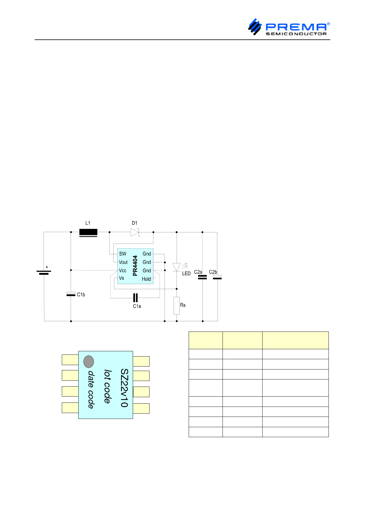
Typical Application Circuit
Pin Description PR4404
SW 1
Vout 2
Vcc 3
Vs 4
8 Gnd(S)
7 Gnd(sub
)
6 Gnd(A)
5 Hold
Pin No
1
2
3
4
5
6
7
8
Pin Name
SW
Vout
Vcc
Vs
Hold
Gnd (A)
Gnd (sub)
Gnd (S)
Pin Function
Description
driver output
output voltage, rectified
battery supply input
LED cathode / current
sense resistor
shutdown
ground (analog)*
ground (substrate)*
ground (power)*
*Pins 6, 7, 8 must all be connected.
© PREMA Semiconductor GmbH 2008
Page 1/12
PRELIMINARY DATA
Rev 3408
Free Datasheet http://www.datasheet4u.com/
1 page 
LED DRIVER PR4404
B. Supply voltage 1...2V - target current 150mA - one LED
Rs = 1.33 Ω , L1 = 1.0µH / 1.5µH with Isat=2.5A
Output Current vs. Supply Voltage
180
160
140
120
100
1.0 µH
80 1.5 µH
60
40
20
0
0,8 1 1,2 1,4 1,6 1,8 2 2,2
Supply Voltage (V)
Output Power vs. Supply Voltage
600
500
400
300
200
100
0
0,8 1 1,2 1,4 1,6 1,8 2 2,2
Supply Voltage (V)
1.0 µH
1.5 µH
80
70
60
50
40
30
20
10
0
0,8
Efficiency vs. Supply Voltage
1.0 µH
1.5 µH
1 1,2 1,4 1,6 1,8 2 2,2
Supply Voltage (V)
Frequency vs. Supply Voltage
Average input current
800 800
700 700
600 600
500 500
400
1.0 µH
400
1.0 µH
1.5 µH
1.5 µH
300 300
200 200
100 100
0
0,8 1 1,2 1,4 1,6 1,8 2 2,2
Supply Voltage (V)
0
0,8 1 1,2 1,4 1,6 1,8 2 2,2
Supply Voltage (V)
The peak input current is approximately twice the average input current.
At some conditions this current is close to the SW current maximum rating.
The allowed ambient temperature range is restricted by the maximum junction
temperature rating!
© PREMA Semiconductor GmbH 2008
Page 5/12
PRELIMINARY DATA
Rev 3408
Free Datasheet http://www.datasheet4u.com/
5 Page 
LED DRIVER PR4404
Calculation of maximum ambient temperature
Under some operating conditions, especially at high voltage transfer ratios and with low
inductances, the IC can get into thermally critical states.
The following formula gives a rough estimtation of the maximum temperature at which the
circuit can be operated.
Pout: output power (measured, or estimated from diagram)
η: efficiency (measured, or estimated from diagram)
PIC: total power dissipation in IC
PIC≈ 1 ⋅Pout Iout⋅Vsense
This formula assumes that the power loss occurs inside the IC and the current sense resistor, but neglects
the losses in the inductor, Schottky diode, wiring and capacitors.
TAmax: maximum ambient temperature
TJmax: maximum junction temperature (see Absolute Maximum Ratings)
ΘJA: thermal resistance of package (see Electrical Characteristics)
TAmax: maximum ambient temperature
T Amax= TJmax JA⋅Ptotal
Example:
According to the diagrams, with a target current of 300mA, a 1.5µH inductor and one LED at the output, at
Vcc=2.2V the actual output power is 950mW, and the efficiency is 70%.
The power dissipated inside the IC can be estimated to
PIC ≈ 0.43 · 0.95W - 0.3A · 0.2V = 0.40W - 0.06W = 0.34W
Then the maximum ambient temperature is
TAmax = 125°C - 160K/W·0.34W = 70°C
For highest reliability a permanent operation near the thermal limits should be avoided.
Actual operating limits will depend on many factors. E.g. a PCB design with good heat spreading and forced
air convection may improve the situation, but a thermally sealed casing or heating from the LED or battery will
make it worse.
Also the efficiency in the actual application may differ from the values given in the diagrams.
With decreasing supply voltage the voltage transfer ratio and therefore the input current
rises, and the efficiency falls. As a consequence, the thermal load on the IC increases as
the supply voltage falls.
Therefore battery operated circuits must be designed that while discharging the battery no
critical state can occur.
© PREMA Semiconductor GmbH 2008
Page 11/12
PRELIMINARY DATA
Rev 3408
Free Datasheet http://www.datasheet4u.com/
11 Page | ||
| Páginas | Total 12 Páginas | |
| PDF Descargar | [ Datasheet PR4404.PDF ] | |
Hoja de datos destacado
| Número de pieza | Descripción | Fabricantes |
| PR4401 | (PR4401 / PR4402) 0.9V Boost Driver | PREMA |
| PR4402 | (PR4401 / PR4402) 0.9V Boost Driver | PREMA |
| PR4404 | LED DRIVER | PREMA |
| Número de pieza | Descripción | Fabricantes |
| SLA6805M | High Voltage 3 phase Motor Driver IC. |
Sanken |
| SDC1742 | 12- and 14-Bit Hybrid Synchro / Resolver-to-Digital Converters. |
Analog Devices |
|
DataSheet.es es una pagina web que funciona como un repositorio de manuales o hoja de datos de muchos de los productos más populares, |
| DataSheet.es | 2020 | Privacy Policy | Contacto | Buscar |