|
|
|
PDF 71M6545H Data sheet ( Hoja de datos )
| Número de pieza | 71M6545H | |
| Descripción | Metrology Processors | |
| Fabricantes | Teridian Semiconductor | |
| Logotipo | ||
Hay una vista previa y un enlace de descarga de 71M6545H (archivo pdf) en la parte inferior de esta página. Total 30 Páginas | ||
|
No Preview Available !
19-5378; Rev 1.0; 4/11
A Maxim Integrated Products Brand
71M6545/71M6545H
Metrology Processors
DATA SHEET
April 2011
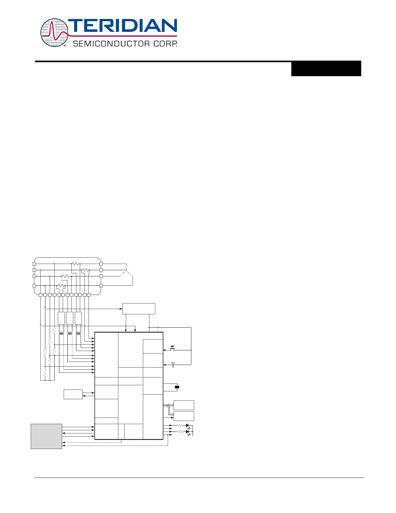
GENERAL DESCRIPTION
FEATURES
The 71M6545/71M6545H metrology processors are based on
Teridian’s 4th-generation metering architecture supporting the
71M6xxx series of isolated current sensing products that offer
drastic reduction in component count, immunity to magnetic
tampering, and unparalleled reliability. The 71M6545/71M6545H
integrate our Single Converter Technology® with a 22-bit delta-
sigma ADC, a customizable 32-bit computation engine (CE) for
core metrology functions, as well as a user-programmable 8051-
compatible application processor (MPU) core with up to 64KB
flash and up to 5KB RAM.
An external host processor can access metrology functions di-
rectly through the SPI™ interface, or alternatively through the
embedded MPU core in applications requiring metrology data
capture, storage, and preprocessing within the metrology
subsystem. In addition, the devices integrate an RTC, DIO, and
UART. A complete array of ICE and development tools,
programming libraries, and reference designs enable rapid
development and certification of meters that meet all ANSI and
IEC electricity metering standards worldwide.
• Up to < 0.1% Accuracy Over 2000:1
Current Range
• Exceeds IEC 62053/ANSI C12.20 Standards
• Seven Sensor Inputs with Neutral Current
Measurement, Differential Mode Selectable
for Current Inputs
• Selectable Gain of 1 or 8 for One Current
Input to Support Shunts
• High-Speed Wh/VARh Pulse Outputs with
Programmable Width
• Flash/RAM Size
32KB/3KB (71M6545)
64KB/5KB (71M6545H)
• Up to Four Pulse Outputs with Pulse Count
• Four-Quadrant Metering, Phase
Sequencing
• Digital Temperature Compensation
Metrology Compensation
Shunt Resistor Sensors
C
NEUTRAL
B
A
LOAD
Accurate RTC for TOU Functions with
Automatic Temperature Compensation
for Crystal in All Power Modes
• Independent 32-Bit Compute Engine
• 46–64Hz Line Frequency Range with the
Same Calibration
POWER SUPPLY
www.DataSheet4U.net
This system is referenced to Neutral
NEUTRAL
HOST
Pulse Transformers
C
B
A
SPI_CKI
SPI_DI
SPI_DO
SPI_CSZ
XFER_BUSY
SAG
MUX and ADC
IADC0
IADC1
} IN*
VADC10 (VC)
IADC6
IADC7
} IC
VADC9 (VB)
IADC4
IADC5
}
IB
VADC8(VA)
IADC2
IADC3
} IA
V3P3A V3P3SYS GNDA GNDD
PWR MODE
CONTROL
TERIDIAN
PB
71M6545/H REGULATOR
TEMPERATURE
SENSOR
VBAT_RTC
BATTERY
MONITOR
VREF
SERIAL PORT
RX
TX
FLASH
MEMORY
RAM
MPU
RTC
TIMERS
OSCILLATOR/
PLL XIN
XOUT
DIO, PULSES,
LEDs
DIO
ICE
T
SPI INTERFACE
M
U
COMPUTE
ENGINE
X
V3P3D
WPULSE
XPULSE
RPULSE
YPULSE
10/7/2010
RTC
BATTERY
32 kHz
24
DIO
I2C or µWire
EEPROM
PULSES 3.3 VDC
*IN = Optional Neutral Current
• Phase Compensation (±7°)
• 1µA Supply Current in Sleep Mode
• Flash Security
• In-System Program Update
• 8-Bit MPU (80515), Up to 5 MIPS, for
Optional Implementation of Postprocessing
and Host Support Functions (Optional Use)
• Up to 29 DIO Pins
• Hardware Watchdog Timer (WDT)
• I2C/MICROWIRE® EEPROM Interface
• SPI Interface for Host:
Full Access to Shared Memory Space
Flash Program Capability
• UART
• Industrial Temperature Range
• 64-Pin Lead(Pb)-Free LQFP Package
Single Converter Technology is a registered trademark of Maxim Integrated Products, Inc.
SPI is a trademark of Motorola, Inc.
MICROWIRE is a registered trademark of National Semiconductor Corp.
v1.0 © 2008–2011 Teridian Semiconductor Corporation 1
1 page 
PDS_6545_009
Data Sheet 71M6545/H
Figures
Figure 1: IC Functional Block Diagram.....................................................................................................9
Figure 2: AFE Block Diagram (Shunts: One-Local, Three-Remotes) ...................................................... 12
Figure 3. AFE Block Diagram (Four CTs)............................................................................................... 13
Figure 4: States in a Multiplexer Frame (MUX_DIV[3:0] = 6) .................................................................. 17
Figure 5: States in a Multiplexer Frame (MUX_DIV[3:0] = 7) .................................................................. 17
Figure 6: General Topology of a Chopped Amplifier............................................................................... 21
Figure 7: CROSS Signal with CHOP_E = 00........................................................................................... 21
Figure 8: RTM Timing ............................................................................................................................ 26
Figure 9. Pulse Generator FIFO Timing ................................................................................................. 28
Figure 10: Samples from Multiplexer Cycle (Frame)............................................................................... 29
Figure 11: Accumulation Interval............................................................................................................ 29
Figure 12: Interrupt Structure................................................................................................................. 45
Figure 13: Automatic Temperature Compensation ................................................................................. 52
Figure 14: Connecting an External Load to DIO Pins ............................................................................. 57
Figure 15: 3-wire Interface. Write Command, HiZ=0.............................................................................. 59
Figure 16: 3-wire Interface. Write Command, HiZ=1.............................................................................. 59
Figure 17: 3-wire Interface. Read Command......................................................................................... 59
Figure 18: 3-Wire Interface. Write Command when CNT=0................................................................... 59
Figure 19: 3-wire Interface. Write Command when HiZ=1 and WFR=1.................................................. 60
Figure 20: SPI Slave Port - Typical Multi-Byte Read and Write operations.............................................. 61
Figure 21: Voltage, Current, Momentary and Accumulated Energy......................................................... 66
Figure 22: Data Flow ............................................................................................................................. 70
Figure 23: Resistive Voltage Divider (Voltage Sensing).......................................................................... 71
Figure 24. CT with Single-Ended Input Connection (Current Sensing).................................................... 71
Figure 25: CT with Differential Input Connection (Current Sensing) ........................................................ 71
Figure 26: Differential Resistive Shunt Connections (Current Sensing)................................................... 71
Figure 27: System Using Three-Remotes and One-Local (Neutral) Sensor ............................................ 72
Figure 28. System Using Current Transformers ..................................................................................... 73
Figure 29: I2C EEPROM Connection...................................................................................................... 79
Figure 30: Connections for the UART .................................................................................................... 79
Figure 31: External Components for the RESET Pin: Push-Button (Left), Production Circuit (Right) ....... 80
Figure 32: External Components for the Emulator Interface ................................................................... 80
www.DataSheet4U.net
Figure 33. Trim Fuse Bit Mapping .......................................................................................................... 98
Figure 34: CE Data Flow: Multiplexer and ADC.................................................................................... 111
Figure 35: CE Data Flow: Scaling, Gain Control, Intermediate Variables for one Phase........................ 111
Figure 36: CE Data Flow: Squaring and Summation Stages................................................................. 112
Figure 37: 64-pin LQFP Package Outline............................................................................................. 126
Figure 38: Pinout for the LQFP-64 Package......................................................................................... 127
Figure 39: I/O Equivalent Circuits......................................................................................................... 131
v1.0
© 2008–2011 Teridian Semiconductor Corporation
5
5 Page 
PDS_6545_009
Data Sheet 71M6545/H
2 HARDWARE DESCRIPTION
2.1 Hardware Overview
The Teridian 71M6545/H single-chip Metrology Processor integrates all primary functional blocks required
to implement a solid-state electricity meter. Included on the chip are:
• An analog front end (AFE) featuring a 22-bit second-order sigma-delta ADC
• An independent 32-bit digital computation engine (CE) to implement DSP functions
• An 8051-compatible microprocessor (MPU) which executes one instruction per clock cycle (80515)
• A precision voltage reference (VREF)
• A temperature sensor for digital temperature compensation:
- Metrology digital temperature compensation (MPU)
- Automatic RTC digital temperature compensation operational in sleep mode (SLP)
• RAM and Flash memory
• A real time clock (RTC)
• A variety of I/O pins
• A power failure interrupt (CE code feature)
• A zero-crossing interrupt (CE code feature)
• Selectable current sensor interfaces for locally-connected sensors as well as isolated sensors (i.e.,
using the 71M6xx3 companion IC with a shunt resistor sensor)
• Resistive Shunt and Current Transformers are supported
In order to implement a poly-phase meter with or without neutral current sensing, one resistive shunt
current sensor may be connected directly (non-isolated) to the 71M6545/H device, while three additional
current shunts are isolated using a companion 71M6xx3 isolated sensor IC. An inexpensive, small size
pulse transformer is used to electrically isolate the 71M6xx3 remote sensor from the 71M6545/H. The
71M6545/H performs digital communications bi-directionally with the 71M6xx3 and also provides power to
the 71M6xx3 through the isolating pulse transformer. Isolated (remote) shunt current sensors are
connected to the differential input of the 71M6xx3. The 71M6545/H may also be used with Current
Transformers; in this case the 71M6xx3 isolated sensors are not required. Included on the 71M6xx3
companion isolator chip are:
• Digital isolation communications interface
• An analog front end (AFE) featuring a 22-bit second-order sigma-delta ADC
• A precision voltage reference (VREF)
• A temperature sensor (for current-sensing digital temperature compensation)
•www.DataSheet4U.net A fully differential shunt resistor sensor input
• A pre-amplifier to optimize shunt current sensor performance
• Isolated power circuitry obtains dc power from pulses sent by the 71M6545/H
In a typical application, the 32-bit compute engine (CE) of the 71M6545/H sequentially processes the
samples from the voltage inputs on analog input pins and performs calculations to measure active energy
(Wh) and reactive energy (VARh), as well as A2h, and V2h for four-quadrant metering. These measurements
are then accessed by the host processor via the SPI or by the on-chip MPU, to be processed further and
output using either the peripheral devices available to the on-chip MPU or by the host processor.
In addition to advanced measurement functions, the real time clock (RTC) function allows the 71M6545/H to
record time of use (TOU) metering information for multi-rate applications and to time-stamp tamper or other
events. An automatic RTC temperature compensation circuit operates in all power states including when the
MPU is halted, and continues to compensate using back-up battery power during power outages
(VBAT_RTC pin).
In addition to the temperature-trimmed ultra-precision voltage reference, the on-chip digital temperature
compensation mechanism includes a temperature sensor and associated controls for correction of unwanted
temperature effects on metrology and RTC accuracy (i.e., to meet the requirements of ANSI and IEC
standards). Temperature-dependent external components such as the crystal, current transformers
(CTs), Current Shunts and their corresponding signal conditioning circuits can be characterized and their
v1.0
© 2008–2011 Teridian Semiconductor Corporation
11
11 Page | ||
| Páginas | Total 30 Páginas | |
| PDF Descargar | [ Datasheet 71M6545H.PDF ] | |
Hoja de datos destacado
| Número de pieza | Descripción | Fabricantes |
| 71M6545 | Metrology Processors | Teridian Semiconductor |
| 71M6545 | Metrology Processors | Maxim Integrated |
| 71M6545H | Metrology Processors | Teridian Semiconductor |
| 71M6545H | Metrology Processors | Maxim Integrated |
| Número de pieza | Descripción | Fabricantes |
| SLA6805M | High Voltage 3 phase Motor Driver IC. |
Sanken |
| SDC1742 | 12- and 14-Bit Hybrid Synchro / Resolver-to-Digital Converters. |
Analog Devices |
|
DataSheet.es es una pagina web que funciona como un repositorio de manuales o hoja de datos de muchos de los productos más populares, |
| DataSheet.es | 2020 | Privacy Policy | Contacto | Buscar |