|
|
|
PDF STRW6252D Data sheet ( Hoja de datos )
| Número de pieza | STRW6252D | |
| Descripción | 60 W-Universal Input/40 W-230 Vac Input PWM Switching Regulators | |
| Fabricantes | Sanken Electric | |
| Logotipo | ||
Hay una vista previa y un enlace de descarga de STRW6252D (archivo pdf) en la parte inferior de esta página. Total 15 Páginas | ||
|
No Preview Available !
STR-W6252Dwww.DataSheet4U.com
60W-Universal Input/40W-230 Vac Input
PWM Switching Regulators
Features and Benefits
▪ Overcurrent protection (OCP) with ac input voltage
compensation function; no additional peripheral circuits
required—minimizes dependency of OCP on ac input
▪ Overload protection (OLP) with integrated timer reduces
power stress (temperature rise) at overload condition,
requires no peripheral components
▪ Avalanche-guaranteed MOSFET improves device
capability of withstanding excess surge voltage,
providing a simple surge absorber circuit without
breakdown voltage derating
▪ Start-up circuit eliminates the need for a start-up resistor,
and helps to reduce input power consumption
Continued on the next page…
Package: TO-220
Description
The STR-W6200D series are current-mode PWM ICs that
incorporate controller chips. These devices are manufactured
using a proprietary high-voltage BCD process, and avalanche-
guaranteed MOSFETs. These elements allow power supply
systems designs that are highly reliable and simple, with fewer
peripheral components. These ICs also provide Auto-Burst
mode operation, which lowers input power requirements at
light loads, and improves efficiency over the entire load range
and universal-input range.
Applicatons include:
▪ TV set top box
▪ LCD PC monitor, LCD TV
▪ Printer, scanner
▪ General consumer, PC, and industrial applications
requiring SMPS power supply with standby mode
Not to scale
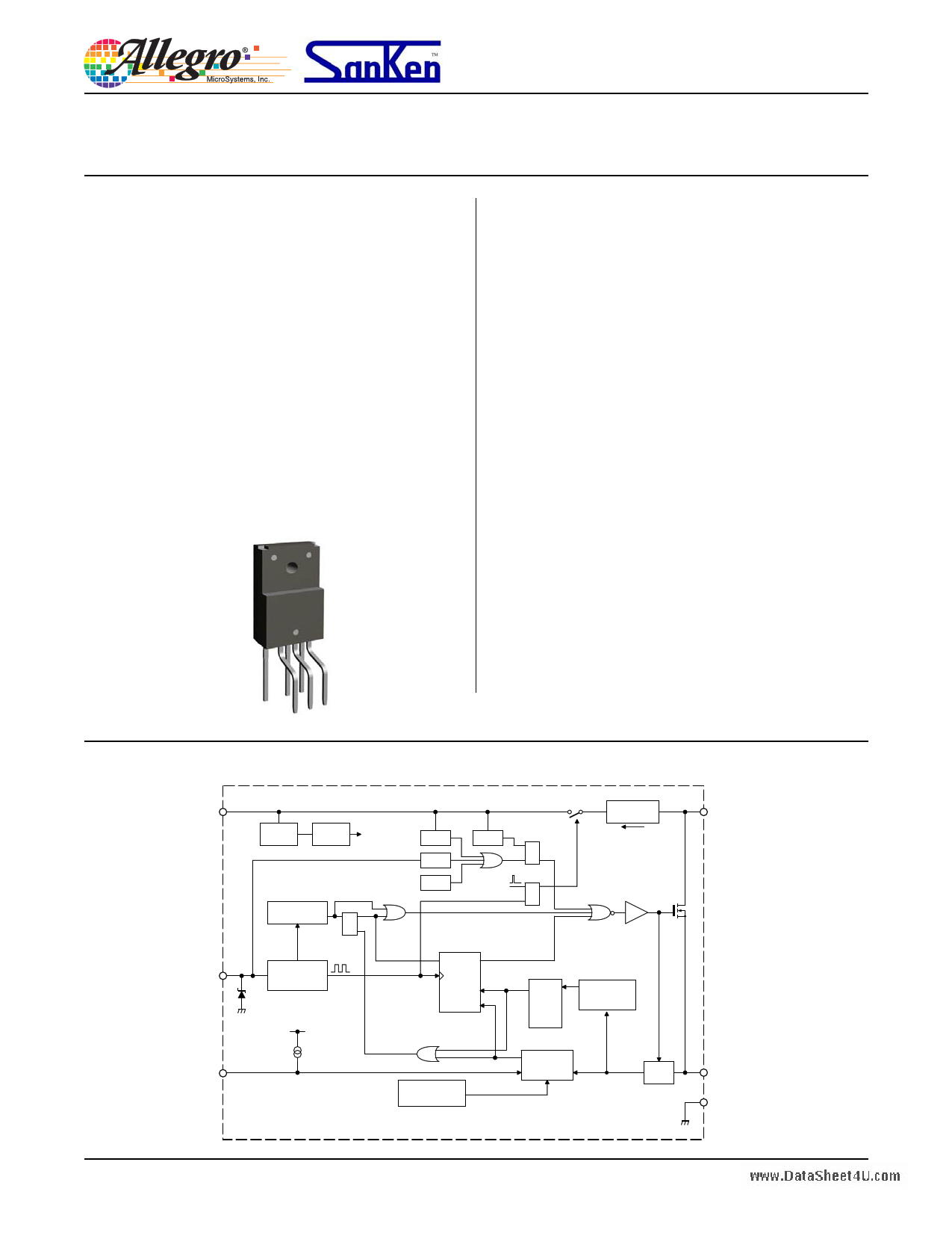
Functional Block Diagram
VCC
UVLO
15.5 V/ 8.9 V
REG
VREG
PWM OSC
DMAX 75%
SQ
R
28.5 V OVP
7.1 V ELP
TSD
7.1 V
RST
R
SQ
RQ
S
STARTUP
Istartup
=1.6 mA
DRV
FM/ELP
12 V
FB
Frequency
Modulation
7.8 V
160 μA
S2 Q
OLP
CK
tOLP = S1
tFM×32 R
Slope
Compensation
OCP
Drain Peak
Current
Compensation
Feedback
Control
LEB
D/ST
S/OCP
GND
28103.52
1 page 
STR-W6252D
60 W-Universal Input/40 W-230 Vac Inputwww.DataSheet4U.com
PWM Switching Regulators
ELECTRICAL CHARACTERISTICS valid at VCC = 18 V, TA = 25°C, unless otherwise specified
Characteristic
Symbol Terminal
Test Conditions
Power Supply Start-up Operation
Operation Start Voltage
VCC(ON)
Operation Stop Voltage
VCC(OFF)
Circuit Current in Operation
ICC(ON)
4-5
(VCC voltage at which operation starts) Measurement
circuit 1, VCC = 0 through 13.9 through 17.1 V
4-5
(VCC voltage at which operation stops) Measurement
circuit 1, VCC = 17.1 through 9.8 to 8.0 V
4-5
(Inflow current into VCC terminal in oscillation)
Measurement circuit 1
Circuit Current in Non-Oscillation
ICC(STOP)
4-5
(Inflow current into VCC terminal at VFB = 0 V)
Measurement circuit 1
Circuit Current in Non-Operation
Start-up Current
Bias Assist Voltage
ICC(OFF)
Istartup
VBIAS
4-5
(Inflow current into VCC terminal prior to oscillation)
Measurement circuit 1, VCC = 13.8
4-5
(Inflow current into D/ST terminal) Measurement
circuit 7, VCC = 0, D/ST = 450 V
(VCC voltage at which Istartup starts, and IstartupBias
4-5 begins) Measurement circuit 7, VCC = 17.1 through
13.6 to 16.8 V
Operating Characteristics
FM/ELP High Threshold Voltage
VFM(H)
7-5
(FM/ELP terminal voltage at which IFM changes from
–13 μA to 13 μA) Measurement circuit 2
FM/ELP Low Threshold Voltage
FM/ELP Voltage Hysteresis
FM/ELP Outflow Current1
VFM(L)
VFMhys
IFMsrc
7-5
(FM/ELP terminal voltage at which IFM changes from
13 μA to –13 μA) Measurement circuit 2
7-5 (VFM(H) – VFM(L)) Measurement circuit 2
7-5
(FM/ELP terminal outflow current at VFM = VFM(L))
Measurement circuit 2
FM/ELP Inflow Current1
Average Switching Frequency
IFMsink
fOSC(av)
7-5
(FM/ELP terminal inflow current at VFM = VFM(H))
Measurement circuit 2
1-5
(D/ST terminal average oscillation frequency)
Measurement circuit 2
Frequency Jitter Deviation
Maximum Duty Cycle
∆f
DMAX
1-5 fOSC (peak-to-peak) Measurement circuit 2
1-5
(Maximum width of the low portion of the D/ST
terminal waveform) Measurement circuit 2
FB Maximum Feedback Current1
IFB(MAX)
6-5
(FB terminal outflow current at VFB = 0 V)
Measurement circuit 3
Burst Threshold Voltage
Slope Compensation Start-up
Duty Cycle
Vburst(th)
DSLP
Set VFM = 0 V and decrease VFB (Vburst(th) is the FB
6-5 terminal voltage level at which D/ST changes from
low to high) Measurement circuit 3
6-5
DSLP = (t3 / t4) × 100 (see figure for measurement
circuit 4 for values of t) Measurement circuit 4
Slope Compensation Rate
SLP
6-5
SLP = 0.02 / (t2 – t1) (see figure for measurement
circuit 4 for values of t) Measurement circuit 4
Min.
13.9
8.0
–
–
–
–0.9
13.6
4.0
2.4
1.4
–17.4
8.6
60
4.8
71
–220
0.99
–
–22
Typ.
15.5
8.9
1.4
0.8
5
–1.6
15.2
4.5
2.8
1.7
–13
13
67
6.9
75
–160
1.10
27
–17
Max
17.1
9.8
2.8
1.3
20
–2.3
16.8
5.0
3.2
1.8
–8.6
17.4
74
9
79
–100
1.21
–
–12
Units
V
V
mA
mA
μA
mA
V
V
V
V
μA
μA
kHz
kHz
%
μA
V
%
mV/μs
Continued on next page…
Allegro MicroSystems, Inc.
115 Northeast Cutoff, Box 15036
Worcester, Massachusetts 01615-0036 (508) 853-5000
www.allegromicro.com
5
5 Page 
STR-W6252D
60 W-Universal Input/40 W-230 Vac Inputwww.DataSheet4U.com
PWM Switching Regulators
10.0 ±0.2
Gate Burr
PACKAGE DIMENSIONS, TO-220
4.2 ±0.2
2.8 ±0.2
Branding
XXXXXXXX
XXXXXXXX
1.34
+0.2
–0.1
1.74
+0.2
–0.1
6×P1.27 ±0.15 = 7.62 ±0.15
Terminal dimensions at case surface
0.45
+0.2
–0.1
2.6 ±0.1
Terminal dimension at case surface
5.08 ±0.6
Terminal dimension at lead tips
1234567
Gate burr: 0.3 mm (max.)
Terminal core material: Cu
Terminal treatment: Ni plating and solder dip
Heat sink material: Cu
Heat sink treatment: Ni plating
Leadform: 2003
Weight (approximate): 2.3 g
Dimensions in millimeters
Drawing for reference only
Branding codes (exact appearance at manufacturer discretion):
1st line, type: W6252
2nd line, lot: YMDD R
Where: Y is the last digit of the year of manufacture
M is the month (1 to 9, O, N, D)
DD is the 2-digit date
R is the manufacturer registration symbol
Leadframe plating Pb-free. Device composition
complies with the RoHS directive.
Allegro MicroSystems, Inc.
115 Northeast Cutoff, Box 15036
Worcester, Massachusetts 01615-0036 (508) 853-5000
www.allegromicro.com
11
11 Page | ||
| Páginas | Total 15 Páginas | |
| PDF Descargar | [ Datasheet STRW6252D.PDF ] | |
Hoja de datos destacado
| Número de pieza | Descripción | Fabricantes |
| STRW6252D | 60 W-Universal Input/40 W-230 Vac Input PWM Switching Regulators | Sanken Electric |
| Número de pieza | Descripción | Fabricantes |
| SLA6805M | High Voltage 3 phase Motor Driver IC. |
Sanken |
| SDC1742 | 12- and 14-Bit Hybrid Synchro / Resolver-to-Digital Converters. |
Analog Devices |
|
DataSheet.es es una pagina web que funciona como un repositorio de manuales o hoja de datos de muchos de los productos más populares, |
| DataSheet.es | 2020 | Privacy Policy | Contacto | Buscar |