|
|
|
PDF 8724E Data sheet ( Hoja de datos )
| Número de pieza | 8724E | |
| Descripción | MAX8724E | |
| Fabricantes | Maxim Integrated Products | |
| Logotipo | ||
Hay una vista previa y un enlace de descarga de 8724E (archivo pdf) en la parte inferior de esta página. Total 29 Páginas | ||
|
No Preview Available !
19-2764; Rev 4; 7/05
EVAALVUAAILTAIOBNLEKIT
Low-Cost Multichemistry Battery Chargers
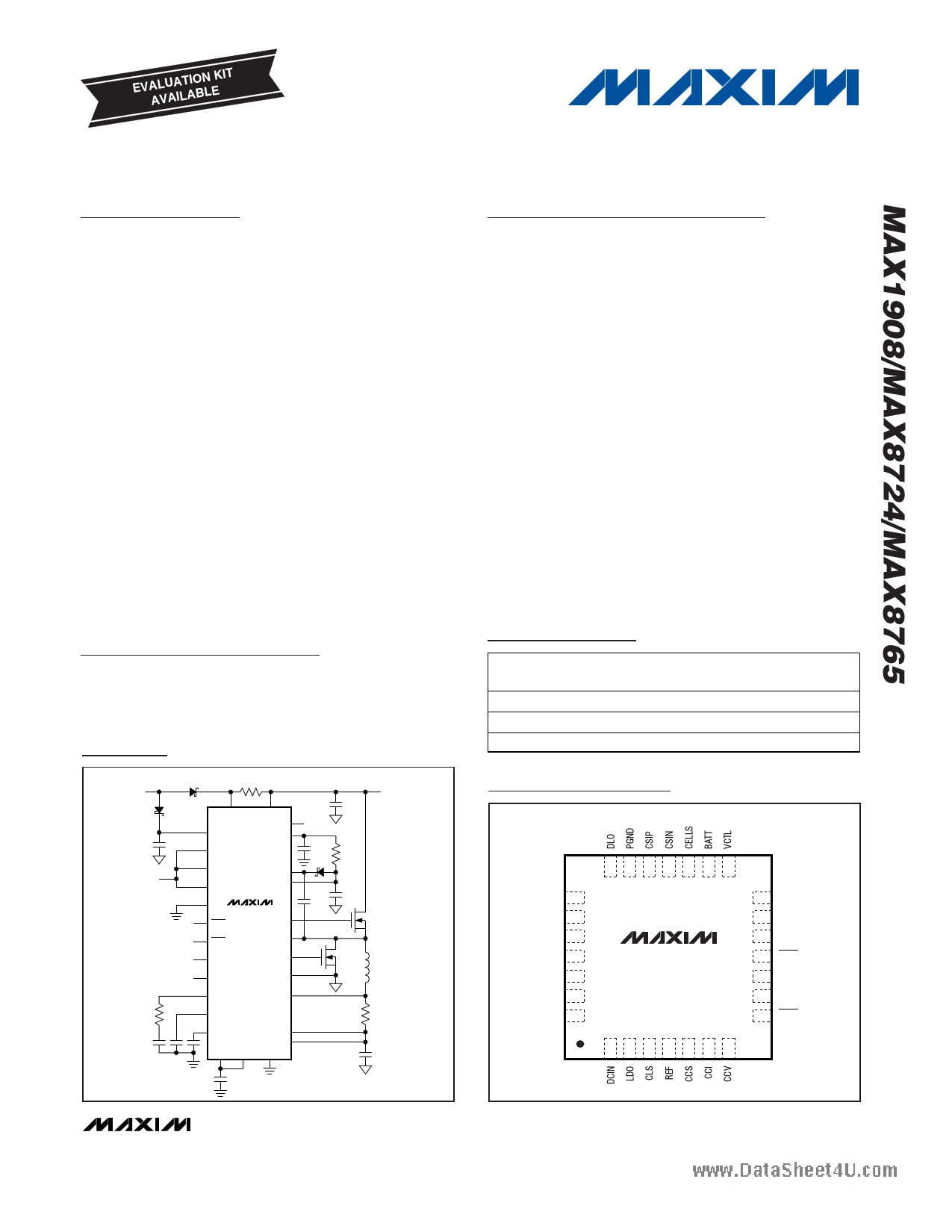
General Description
www.dTahtaeshMeeAt4Xu1.9co0m8/MAX8724/MAX8765 highly integrated, multi-
chemistry battery-charger control ICs simplify the construc-
tion of accurate and efficient chargers. These devices use
analog inputs to control charge current and voltage, and
can be programmed by the host or hardwired. The
MAX1908/MAX8724/MAX8765 achieve high efficiency
using a buck topology with synchronous rectification.
The MAX1908/MAX8724/MAX8765 feature input current
limiting. This feature reduces battery charge current when
the input current limit is reached to avoid overloading the
AC adapter when supplying the load and the battery
charger simultaneously. The MAX1908/MAX8724/
MAX8765 provide outputs to monitor current drawn from
the AC adapter (DC input source), battery-charging cur-
rent, and the presence of an AC adapter. The MAX1908’s
conditioning charge feature provides 300mA to safely
charge deeply discharged lithium-ion (Li+) battery packs.
The MAX1908 includes a conditioning charge feature
while the MAX8724/MAX8765 do not.
The MAX1908/MAX8724/MAX8765 charge two to four
series Li+ cells, providing more than 5A, and are avail-
able in a space-saving, 28-pin, thin QFN package (5mm
× 5mm). An evaluation kit is available to speed designs.
Applications
Notebook and Subnotebook Computers
Personal Digital Assistants
Handheld Terminals
Minimum Operating Circuit
AC ADAPTER
INPUT
0.01Ω
TO EXTERNAL
LOAD
LDO
FROM HOST μP
CSSP
DCIN
REFIN
CSSN
CELLS
LDO
VCTL BST
ICTL DLOV
ACIN
ACOK
SHDN
MAX1908
MAX8724
MAX8765
DHI
LX
ICHG DLO
IINP PGND
CCV CSIP
CCI
CCS
REF CLS
CSIN
BATT
GND
10μH
0.015Ω
BATT+
Features
♦ ±0.5% Output Voltage Accuracy Using Internal
Reference (0°C to +85°C)
♦ ±4% Accurate Input Current Limiting
♦ ±5% Accurate Charge Current
♦ Analog Inputs Control Charge Current and
Charge Voltage
♦ Outputs for Monitoring
Current Drawn from AC Adapter
Charging Current
AC Adapter Presence
♦ Up to 17.6V Battery-Voltage Set Point
♦ Maximum 28V Input Voltage
♦ > 95% Efficiency
♦ Shutdown Control Input
♦ Charge Any Battery Chemistry
Li+, NiCd, NiMH, Lead Acid, etc.
Ordering Information
PART
MAX1908ETI
MAX8724ETI
MAX8765ETI
TEMP RANGE PIN-
PACKAGE
-40°C to +85°C 28 Thin QFN
-40°C to +85°C 28 Thin QFN
-40°C to +85°C 28 Thin QFN
PKG CODE
T2855-6
T2855-6
T2855-6
Pin Configuration
TOP VIEW
DLOV 22
LX 23
BST 24
DHI 25
CSSN 26
CSSP 27
IINP 28
21 20 19 18 17 16 15
MAX1908
MAX8724
MAX8765
14 GND
13 ICTL
12 REFIN
11 ACOK
10 ACIN
9 ICHG
8 SHDN
1 23 4 567
THIN QFN
________________________________________________________________ Maxim Integrated Products 1
For pricing, delivery, and ordering information, please contact Maxim/Dallas Direct! at
1-888-629-4642, or visit Maxim’s website at www.maxim-ic.com.
1 page 
Low-Cost Multichemistry Battery Chargers
ELECTRICAL CHARACTERISTICS (continued)
www.d(aVtaDsChIeNe=t4uV.CcoSmSP = VCSSN = 18V, VBATT = VCSIP = VCSIN = 12V, VREFIN = 3V, VVCTL = VICTL = 0.75 x VREFIN, CELLS = float, CLS =
REF, VBST - VLX = 4.5V, ACIN = GND = PGND = 0, CLDO = 1µF, LDO = DLOV, CREF = 1µF; CCI, CCS, and CCV are compensated
per Figure 1a; TA = 0°C to +85°C, unless otherwise noted. Typical values are at TA = +25°C.)
PARAMETER
TRIP POINTS
SYMBOL
CONDITIONS
MIN TYP MAX UNITS
BATT Power-Fail Threshold
BATT Power-Fail Threshold
Hysteresis
ACIN Threshold
ACIN Threshold Hysteresis
ACIN Input Bias Current
SWITCHING REGULATOR
VDCIN falling, referred to VCSIN
(MAX1908/MAX8724 only)
VCSSP falling, referred to VCSIN
(MAX8765 only)
ACIN rising (MAX8765 only)
ACIN rising (MAX1908/MAX8724 only)
0.5% of REF
VACIN = 2.048V
50 100 150
mV
50 100 150
200
2.028
2.007
-1
2.048
2.048
20
2.068
2.089
+1
mV
V
V
mV
µA
DHI Off-Time
VBATT = 16V, VDCIN = 19V,
VCELLS = VREFIN
0.36 0.4 0.44
µs
DHI Minimum Off-Time
DHI Maximum On-Time
DLOV Supply Current
BST Supply Current
BST Input Quiescent Current
LX Input Bias Current
LX Input Quiescent Current
DHI Maximum Duty Cycle
VBATT = 16V, VDCIN = 17V,
VCELLS = VREFIN
IDLOV
IBST
DLO low
DHI high
VDCIN = 0, VBST = 24.5V,
VBATT = VLX = 20V
VDCIN = 28V, VBATT = VLX = 20V
VDCIN = 0, VBATT = VLX = 20V
0.24
2.5
99
0.28
5
5
6
0.3
150
0.3
99.9
0.33
7.5
10
15
1
500
1
µs
ms
µA
µA
µA
µA
µA
%
Minimum Discontinuous-Mode
Ripple Current
0.5 A
Battery Undervoltage Charge
Current
Battery Undervoltage Current
Threshold
DHI On-Resistance High
DHI On-Resistance Low
DLO On-Resistance High
DLO On-Resistance Low
VBATT = 3V per cell (RS2 = 15mΩ),
MAX1908 only, VBATT rising
CELLS = GND, MAX1908 only, VBATT rising
CELLS = float, MAX1908 only, VBATT rising
CELLS = VREFIN, MAX1908 only, VBATT rising
VBST - VLX = 4.5V, IDHI = +100mA
VBST - VLX = 4.5V, IDHI = -100mA
VDLOV = 4.5V, IDLO = +100mA
VDLOV = 4.5V, IDLO = -100mA
150
6.1
9.15
12.2
300
6.2
9.3
12.4
4
1
4
1
450
6.3
9.45
12.6
7
3.5
7
3.5
mA
V
Ω
Ω
Ω
Ω
_______________________________________________________________________________________ 5
5 Page 
Low-Cost Multichemistry Battery Chargers
Typical Operating Characteristics (continued)
www.da(Ctaisrchueietto4fuF.ciogmure 1, VDCIN = 20V, TA = +25°C, unless otherwise noted.)
VDCIN
10V/div
VBATT
500mV/div
LINE-TRANSIENT RESPONSE
MAX1908 toc04
INDUCTOR
CURRENT
500mA/div
ICTL = LDO
10ms/div
VCTL = LDO
ICHARGE = 3A
LINE STEP 18.5V TO 27.5V
REF VOLTAGE LOAD REGULATION
0
-0.01
-0.02
-0.03
-0.04
-0.05
-0.06
-0.07
-0.08
-0.09
-0.10
0
100 200 300 400
REF CURRENT (μA)
500
LDO LOAD REGULATION
0
-0.1
-0.2
-0.3
-0.4
-0.5
-0.6
-0.7
-0.8
VLDO = 5.4V
-0.9
-1.0
012345678
LDO CURRENT (mA)
9 10
REF VOLTAGE ERROR vs. TEMPERATURE
0.10
0.08
0.06
0.04
0.02
0
-0.02
-0.04
-0.06
-0.08
-0.10
-40
-15 10 35 60
TEMPERATURE (°C)
85
LDO LINE REGULATION
0.05
0.04 ILDO = 0
0.03 VLDO = 5.4V
0.02
0.01
0
-0.01
-0.02
-0.03
-0.04
-0.05
8
10 12 14 16 18 20 22 24 26 28
VIN (V)
EFFICIENCY vs. CHARGE CURRENT
100
90
80
70 VBATT = 16V
60 VBATT = 12V
50
40 VBATT = 8V
30
20
10
0
0.01
0.1 1
CHARGE CURRENT (A)
10
FREQUENCY vs. VIN - VBATT
500
450
400 3 CELLS
350 4 CELLS
300
250
200
150
100
ICHARGE = 3A
VCTL = ICTL = LDO
50
0
0 2 4 6 8 10 12 14 16 18 20 22
(VIN - VBATT) (V)
0.5
0.4
0.3
0.2
0.1
0
-0.1
-0.2
-0.3
-0.4
-0.5
0
OUTPUT V/I CHARACTERISTICS
2 CELLS
3 CELLS
4 CELLS
123
BATT CURRENT (A)
4
BATT VOLTAGE ERROR vs. VCTL
0.08
0.07
0.06
0.05
0.04
0.03
0.02 4 CELLS
0.01
REFIN = 3.3V
NO LOAD
0
0 0.1 0.2 0.3 0.4 0.5 0.6 0.7 0.8 0.9 1.0
VCTL/REFIN (%)
______________________________________________________________________________________ 11
11 Page | ||
| Páginas | Total 29 Páginas | |
| PDF Descargar | [ Datasheet 8724E.PDF ] | |
Hoja de datos destacado
| Número de pieza | Descripción | Fabricantes |
| 8724E | MAX8724E | Maxim Integrated Products |
| Número de pieza | Descripción | Fabricantes |
| SLA6805M | High Voltage 3 phase Motor Driver IC. |
Sanken |
| SDC1742 | 12- and 14-Bit Hybrid Synchro / Resolver-to-Digital Converters. |
Analog Devices |
|
DataSheet.es es una pagina web que funciona como un repositorio de manuales o hoja de datos de muchos de los productos más populares, |
| DataSheet.es | 2020 | Privacy Policy | Contacto | Buscar |