|
|
|
PDF LM1292N Data sheet ( Hoja de datos )
| Número de pieza | LM1292N | |
| Descripción | Video PLL System for Continuous-Sync Monitors | |
| Fabricantes | National Semiconductor | |
| Logotipo | ||
Hay una vista previa y un enlace de descarga de LM1292N (archivo pdf) en la parte inferior de esta página. Total 10 Páginas | ||
|
No Preview Available !
April 1999
LM1292
Video PLL System for Continuous-Sync Monitors
General Description
The LM1292 is a very low jitter, integrated horizontal time
base solution specifically designed to operate in high perfor-
mance, continuous-sync video monitors. It automatically
synchronizes to any H frequency from 22 kHz to 125 kHz
and provides the drive pulse to the high power deflection cir-
cuit.
Available sync processing includes a vertical sync separator
and a composite video sync stripper. An internal sync selec-
tion scheme gives highest priority to separate H and V sync,
then composite sync, and finally sync on video; no external
switching between sync sources is necessary. The LM1292
provides polarity-normalized H/HV and V sync outputs.
The LM1292 design uses an on-chip FVC
(Frequency-to-Voltage Converter) to set the center fre-
quency of the VCO (Voltage-Controlled Oscillator). This
technique allows autosync operation over the entire fre-
quency range using just one optimized set of external com-
ponents.
The system includes a second phase detector which com-
pensates for storage time variation in the horizontal output
transistor; the picture’s horizontal position is thus indepen-
dent of temperature and component variance.
The LM1292 provides DC control pins for H Drive duty cycle
and flyback phase.
Features
n Wide continuous autosync range — 22 kHz–125 kHz
(1:5.7) with no component switching or external
adjustments
n No manufacturing trims required — internal VCO
capacitor trimmed on chip
n No costly high-precision components needed
n Very low phase jitter (below 800 ps at 125 kHz)
n DC controlled H phase and duty cycle
n Video mute pulse for blanking during H frequency
transitions
n Input sync prioritization
n Clamp pulse position and width control
n Continuous clamp pulse output, even with no sync input
n Resistor-programmable minimum and maximum VCO
frequency
n X-ray input disables H drive and mutes video until VCC
powered down
n H drive disabled for VCC < 9.5V
n Horizontal output transistor protected against accidental
turn-on during flyback
n Capacitor-programmable frequency ramping, df vco/dt,
protects H output transistor during scanning mode
changes
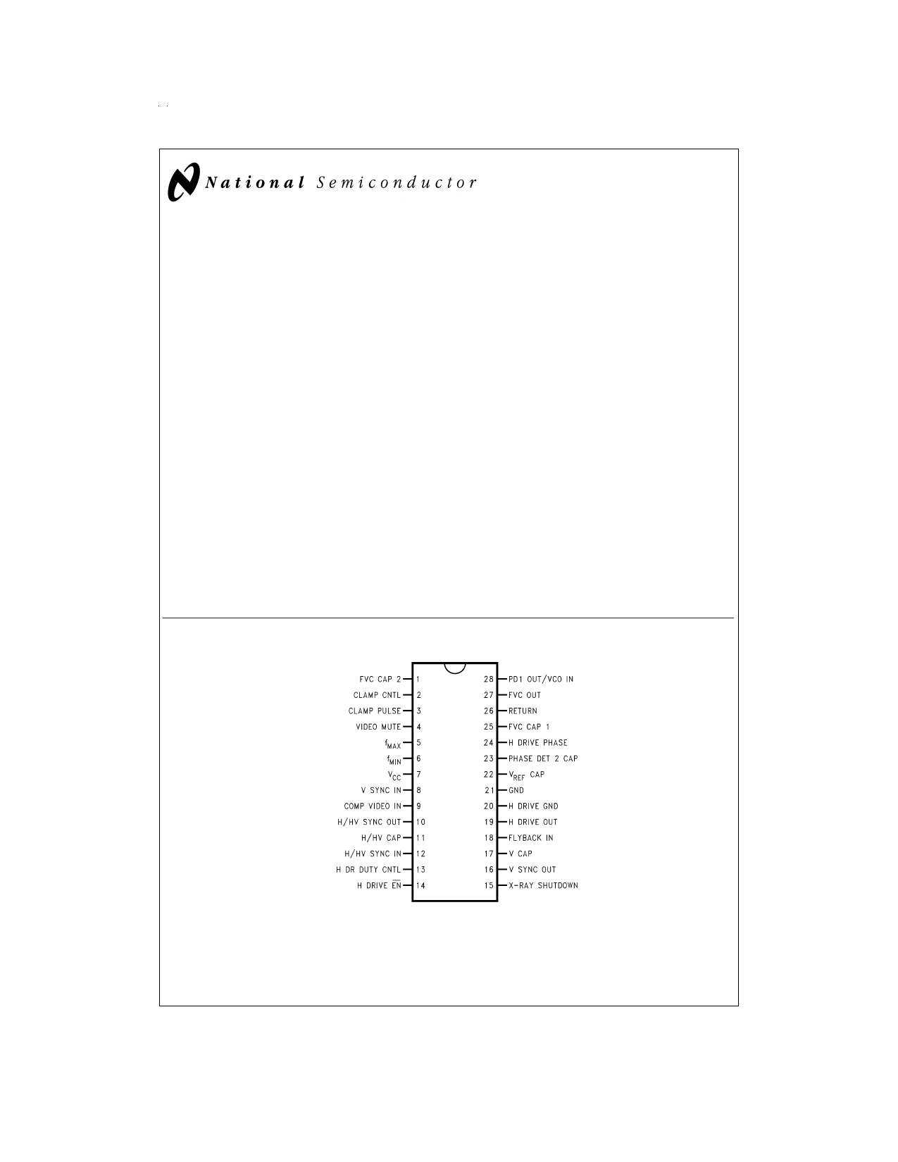
Connection Diagram
DS012844-1
FIGURE 1. Order Number LM1292N
See NS Package Number N28B
© 1999 National Semiconductor Corporation DS012844
www.national.com
1 page 
Block Diagram
DS012844-3
FIGURE 3.
Pin Descriptions
See Figure 4 through Figure 14 for input and output sche-
matics.
Pin 1 — FVC CAP 2: Secondary FVC filter pin. CFVC2 is con-
nected from this pin to ground. The width of the VIDEO
MUTE (pin 4) pulse is controlled by the time constant differ-
ence between the filters at pins 1 and 25.
Pin 2–CLAMP CNTL: This low-impedance current-mode in-
put pin is internally biased to 2V. The direction of current sets
the pulse position (back porch or sync-tip), while the current
magnitude sets the pulse width. In a typical application, a
control voltage of 0V–4V is applied to this pin through a
15 kΩ resistor. A voltage below 2V positions the pulse on the
back porch of the horizontal sync pulse and decreasing volt-
age narrows the pulse. A voltage above 2V sets the pulse on
the H sync-tip (slightly delayed from the leading edge) and
increasing voltage narrows the pulse. At the boundary of the
switchover between the two modes, there is a narrow region
of uncertainty resulting in oscillation, which should be no
problem in most applications.
When there is no H sync in sync-tip mode, the clamp pulse
is generated by the VCO at the frequency preset by pin 6
(fMIN). This feature is intended for use in On Screen Display
systems.
Pin 3 — CLAMP PULSE: Active-low clamp pulse output.
See Figure 4 for the output schematic.
Pin 4 — VIDEO MUTE: This NPN open-collector output pro-
duces an active-low pulse when triggered by a step change
of H sync frequency. See Figure 5 for the output schematic.
Pin 5 — fMAX: A resistor from this pin to ground sets the up-
per frequency limit of the VCO. fMAX is approximately:
Pin 6 — fMIN: A resistor from this pin to ground sets the lower
frequency limit of the VCO. fMIN is approximately:
Pin 7 — VCC: 12V nominal power supply pin. This pin should
be decoupled to pin 21 (GND) via a short path with a cap of
at least 47 µF.
Pin 8 — V SYNC IN: This pin accepts AC-coupled V sync of
either polarity. The pin is internally biased at 5.2V; its input
resistance is approximately 50 kΩ. For best noise immunity,
a resistor of 2 kΩ or less should be connected from the input
side of the coupling cap to pin 21 (GND) via a short path.
See Figure 6 for the input schematic.
Pin 9 — COMP VIDEO IN: The composite video sync strip-
per is active only when no signal is present at pin 12 (H/HV
IN). The signal to pin 9 must have negative-going sync tips
which are at least 0.14V below black level. For best noise im-
munity, a resistor of 2 kΩ or less should be connected from
the input side of the coupling cap to pin 21 (GND) via a short
path. See Figure 7 for the input schematic.
Pin 10 — H/HV SYNC OUT: The sync processor outputs
active-low H/HV sync derived from the active sync input (pin
9 or pin 12). Pin 10 stays low in the absence of sync input.
See Figure 4 for the output schematic.
Pin 11 — H/HV CAP: A capacitor is connected from this pin
to ground for detecting the polarity and existence of H/HV
sync at pin 12.
Pin 12 — H/HV SYNC IN: This pin accepts AC-coupled H or
composite sync of either polarity. For best noise immunity, a
5 www.national.com
5 Page | ||
| Páginas | Total 10 Páginas | |
| PDF Descargar | [ Datasheet LM1292N.PDF ] | |
Hoja de datos destacado
| Número de pieza | Descripción | Fabricantes |
| LM1292 | Video PLL System for Continuous-Sync Monitors | National Semiconductor |
| LM1292 | LM1292 Video PLL System for Continuous-Sync Monitors | Texas Instruments |
| LM1292N | Video PLL System for Continuous-Sync Monitors | National Semiconductor |
| Número de pieza | Descripción | Fabricantes |
| SLA6805M | High Voltage 3 phase Motor Driver IC. |
Sanken |
| SDC1742 | 12- and 14-Bit Hybrid Synchro / Resolver-to-Digital Converters. |
Analog Devices |
|
DataSheet.es es una pagina web que funciona como un repositorio de manuales o hoja de datos de muchos de los productos más populares, |
| DataSheet.es | 2020 | Privacy Policy | Contacto | Buscar |