|
|
|
PDF AN1112 Data sheet ( Hoja de datos )
| Número de pieza | AN1112 | |
| Descripción | THREE-PHASE MOTOR CONTROL | |
| Fabricantes | ST Microelectronics | |
| Logotipo | ||
Hay una vista previa y un enlace de descarga de AN1112 (archivo pdf) en la parte inferior de esta página. Total 22 Páginas | ||
|
No Preview Available !
AN1112
APPLICATION NOTE
Three-Phase Motor Control by using ST52x301
Authors: M. Di Guardo, G. Grasso, M. Lo Presti
Introduction
Induction motors with squirrel-cage are widely used in industrial environments because of their low cost
and rotors rugged construction.
The induction motor is a simple and robust machine, but its control migth be a complex task. When ma-
naged directly from the line voltage, the motor operates at nearly a constant speed. To obtain speed and
torque variations, it is necessary to modify both the voltage and the frequency, by using an electronic
www.DataSchoenevt4eUr.tceormmust be used to perform this operation.
The best way to run the motor is by using a PWM sine-wave modulation, but in many applications this
can result very expensive for the complex implementability.
The six-step modulation (square wave) is a low-cost solution that allows to run the motor at various
speeds.
The aim of this application is to describe how ST52x301 can easily work to obtain frequency and voltage
variations in the Inverter Driver and how to perform a closed loop control.
Speed control by varying stator frequency and voltage
The rotor speed can be controlled by varying the frequency of the stator voltage F. This is possible by
varying Vs in a linear proportion to F.
Varying the stator frequency and voltage is the preferred technique in most variable-speed induction mo-
tor drive applications. This technique is known as V/F=constant.
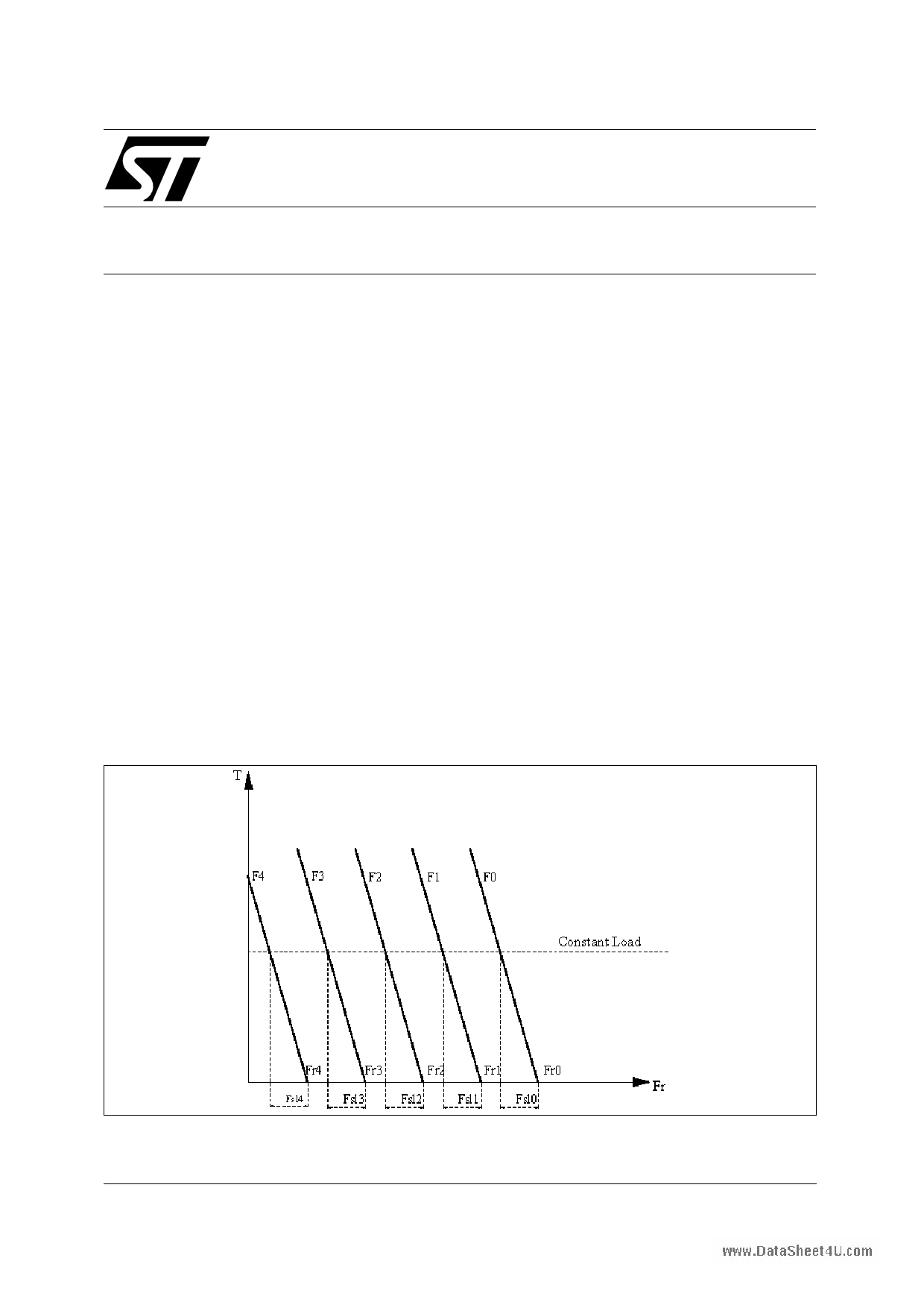
As displayed in figure 1, for a small value of slip frequency (Fsl= Fs-Fr) and for fixed flux values, a linear
relationship between Torque T and Fsl (slip) takes place at any frequency F.
Fig . 1 Torque Speed Characteristics
φ = constant
January 1999
1/ 22
1 page 
Three-Phase Motor Control by using ST52x301
By using this method the line to line r. m. s. voltage is about:
V(rms) = 0.78*Vd*d
where d is the PWM duty cycle
In the following figure is shown the schematic block of the ST52x301 board that allows to reproduce a
six step modulation. The main parts of this system are the microcontroller, the circuit utilized to provide
the bridge control signals (U*, V*, W* and U*, V*, W*) and the three-phase inverter driver.
Fig . 8 - System Schematic block
www.DataSheet4U.com
ST52T301
Ref. A/D PWM
Timer
Digital
I/O
U
V
W
U*
V*
W*
+
U*
V* W*
U* V* W*
-
R
SM
T
Speed
® 5/ 22
5 Page 
Three-Phase Motor Control by using ST52x301
Main Program
The following figure shows the Main Program Window. The first two blocks ("Timer_Int_Setting" and "Ti-
mer_Int_Priority") allow the interrupts mask configuration. In this case, only the Timer is enabled to sup-
ply an interrupt, each time the Timer reaches the counter register value. This interrupt is utilized to syn-
chronize the phase switching.
The block "Variables_Initialization" assigns a default value to the global variables while the "Digi-
tal_Port_bit_set" block sets the parallel port U-V-W pins. The following blocks, "Voltage_level_setting"
and "Start_PWM", are used respectively to set and start the PWM signal on ST52x301 Triacout pin.
The "Start_AD" block enables analog to digital converter to work in continuous mode.
By means of the following two blocks, the converted values of measured speed and speed reference are
read and stored into two global variables. The "Error_definition" block performs the error calculation as
folllows:
error=Reference - speed
After a time delay the resulting ’error’ value is sent to the "Fuzzy_controller" Block. This fuzzy block im-
www.DataSphleeemt4eUn.ctsoma fuzzy algorithm which produces the frequency increment or decrement ∆f to be added to the
actual stator frequency, in order to obtain the desidered speed.
Details on this algorithm will be given later on.
Fig . 14 - Program’s Main view
The block named "integrator" updates the current speed and checks for possible under/overflow in the
algebric sum. The "V_F_control" Fuzzy Block is used as fuzzy model of the Voltage-Frequency relations-
hip, whose diagram is shown in fig.2. This fuzzy block outputs a voltage value for each frequency input
value. "Voltage_2_PWM" and "Freq_2_Timer" blocks updates Triac counter register and Timer counter
register, in order to change the PWM mean value and rotor speed.
® 11/ 22
11 Page | ||
| Páginas | Total 22 Páginas | |
| PDF Descargar | [ Datasheet AN1112.PDF ] | |
Hoja de datos destacado
| Número de pieza | Descripción | Fabricantes |
| AN111 | Balanced Summing Amplifier | Analog Devices |
| AN111 | Using the Xicor 16K to 64K Supervisory EEPROMs | Xicor |
| AN1111C | LED | Stanley Electric |
| AN1111R | LED | Stanley Electric |
| Número de pieza | Descripción | Fabricantes |
| SLA6805M | High Voltage 3 phase Motor Driver IC. |
Sanken |
| SDC1742 | 12- and 14-Bit Hybrid Synchro / Resolver-to-Digital Converters. |
Analog Devices |
|
DataSheet.es es una pagina web que funciona como un repositorio de manuales o hoja de datos de muchos de los productos más populares, |
| DataSheet.es | 2020 | Privacy Policy | Contacto | Buscar |