|
|
|
PDF 3946 Data sheet ( Hoja de datos )
| Número de pieza | 3946 | |
| Descripción | Half-bridge Power MOSFET Controller | |
| Fabricantes | Allegro Micro Systems | |
| Logotipo | ||
Hay una vista previa y un enlace de descarga de 3946 (archivo pdf) en la parte inferior de esta página. Total 14 Páginas | ||
|
No Preview Available !
3946
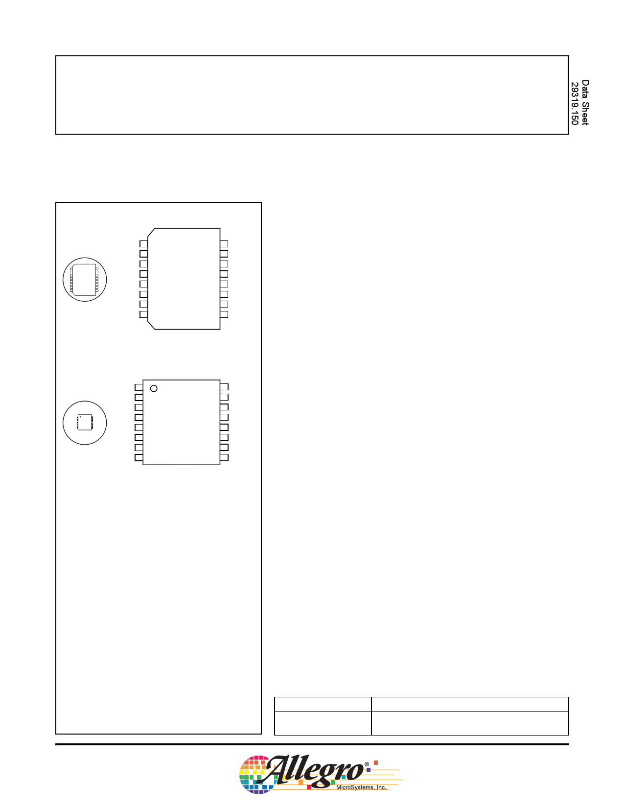
Half-Bridge Power MOSFET Controller
A3946KLB SOIC
Scale 1:1
VREG
CP2
CP1
PGND
GL
S
GH
BOOT
1
2
3
4
5
6
7
8
16 VBB
15 VREF
14 DT
13 LGND
12 RESET
11 IN2
10 IN1
9 ~FAULT
A3946KLP TSSOP with Exposed Thermal Pad
Scale 1:1
VREG
CP2
CP1
PGND
GL
S
GH
BOOT
1
2
3
4
5
6
7
8
16 VBB
15 VREF
14 DT
13 LGND
12 RESET
11 IN2
10 IN1
9 ~FAULT
ABSOLUTE MAXIMUM RATINGS
Load Supply Voltage, VBB ............................. 60 V
Logic Inputs ..................................–0.3 V to 6.5 V
Pin S……. .........................................–4 V to 60 V
Pin GH ...........................................–4 V to 75 V
Pin BOOT….. ................................–0.6 V to 75 V
Pin DT ........................................................ VREF
Pin VREG ......................................–0.6 V to 15 V
Package Thermal Resistance, RJA
A3946KLB..................................... 48°C/W1
A3946KLB..................................... 38°C/W2
A3946KLP ..................................... 44°C/W1
A3946KLP ..................................... 34°C/W2
Operating Temperature Range, TA.. –40°C to +135°C
Junction Temperature, TJ...........................+150°C
Storage Temperature Range, TS....-55°C to +150°C
Notes:
1. Measured on a two-sided PCB with 3 in.2 of
2 oz. copper.
2. Measured on JEDEC standard High-K board.
The A3946 is designed specifically for applications that require
high power unidirectional dc motors, three-phase brushless dc motors, or
other inductive loads. The A3946 provides two high-current gate drive
outputs that are capable of driving a wide range of power N-channel
MOSFETs. The high-side gate driver switches an N-channel MOSFET
that controls current to the load, while the low-side gate driver switches
an N-channel MOSFET as a synchronous rectifier.
A bootstrap capacitor provides the above-battery supply voltage
required for N-channel MOSFETs. An internal charge pump for the
high side allows for dc (100% duty cycle) operation of the half-bridge.
The A3946 is available in a choice of two power packages: a
16-lead SOIC with copper batwing power tab (part number suffix LB),
and a 16-lead TSSOP with exposed thermal pad (suffix LP).
www.DataSheet4U.com
FEATURES
On-chip charge pump for 7 V minimum input supply voltage
High-current gate drive for driving a wide range of
N-channel MOSFETs
Bootstrapped gate drive with charge pump for 100% duty cycle
Overtemperature protection
Undervoltage protection
–40ºC to 135ºC ambient operation
Always order by complete part number:
Part Number
A3946KLB
A3946KLP
Package
16-Lead SOIC; Copper Batwing Power Tab
16-Lead TSSOP; Exposed Thermal Pad
1 page 
3946
Half-Bridge Power MOSFET Controller
Functional Description
VREG. A 13 V output from the on-chip charge pump, used
to power the low-side gate drive circuit directly, provides the
current to charge the bootstrap capacitors for the high-side
gate drive.
The VREG capacitor, CREG, must supply the instantaneous
current to the gate of the low-side MOSFET. A 10 µF, 25 V
capacitor should be adequate. This capacitor can be either
electrolytic or ceramic (X7R).
Diagnostics and Protection. The fault output pin,
~FAULT, goes low (i.e., FAULT = 1) when the RESET line
is high and any of the following conditions are present:
• Undervoltage conditions on VREG (UVREG) or on the
internal logic supply VREF (UVREF). These conditions
set a latched fault.
• A junction temperature > 170°C (OVERTEMP). This con-
dition sets a latched fault.
• An undervoltage on the stored charge of the BOOT capaci-
tor (UVBOOT). This condition does NOT set a latched
fault.
An overtemperature event signals a latched fault, but does
not disable any output drivers, regulators, or logic inputs.
The user must turn off the A3946 (e.g., force the RESET line
low) to prevent damage.
cleared immediately, and remains cleared. If the power is
restored (no UVREG or UVREF), and if no OVERTEMP
fault exists, then the latched fault remains cleared when the
RESET line returns to high. However, FAULT = 1 may still
occur because a UVBOOT fault condition may still exist.
Charge Pump. The A3946 is designed to accommodate
a wide range of power supply voltages. The charge pump
output, VREG, is regulated to 13 V nominal.
In all modes, this regulator is current-limited. When VBB
< 8 V, the charge pump operates as a voltage doubler. When
8 V < VBB< 15 V, the charge pump operates as a voltage
doubler/PWM, current-controlled, voltage regulator. When
VBB>15 V, the charge pump operates as a PWM, current-con-
trolled, voltage regulator. Efficiency shifts, from 80% at VBB=
7 V, to 20% at VBB = 50 V.
CAUTION. Although simple paralleling of VREG supplies
from several A3946s may appear to work correctly, such a
configuration is NOT recommended. There is no assurance
that one of the regulators will not dominate, taking on all of
the load and back-biasing the other regulators. (For example,
this could occur if a particular regulator has an internal refer-
ence voltage that is higher that those of the other regulators,
which would force it to regulate at the highest voltage.)
The power FETs are protected from inadequate gate drive
voltage by undervoltage detectors. Either of the regulator
undervoltage faults (UVREG or UVREF) disable both output
drivers until both voltages have been restored. The high-side
driver is also disabled during a UVBOOT fault condition.
Under many operating conditions, both the high-side (GH)
and low-side (GL) drivers may be off, allowing the BOOT
capacitor to discharge (or never become charged) and create
a UVBOOT fault condition, which in turn inhibits the high-
side driver and creates a FAULT = 1. This fault is NOT
latched. To remove this fault, momentarily turn on GL to
charge the BOOT capacitor.
Sleep Mode/Power Up. In Sleep Mode, all circuits are
disabled in order to draw minimum current from VBB. When
powering up and leaving Sleep Mode (the RESET line is
high), the gate drive outputs stay disabled and a fault remains
asserted until VREF and VREG pass their undervoltage
thresholds. When powering up, before starting the first boot-
strap charge cycle, wait until t = CREG ⁄ 4 (where CREG is in
µF, and t is in ns) to allow the charge pump to stabilize.
When powered-up (not in Sleep Mode), if the RESET line
is low for > 10 µs, the A3946 may start to enter Sleep Mode
(VREF < 4 V). In that case, ~FAULT = 1 as long as the RESET
line remains low.
Latched faults may be cleared by a low pulse, 1 to 10 µs
wide, on the RESET line. Throughout that pulse (despite
a possible UVBOOT), FAULT = 0; also the fault latch is
If the RESET line is open, the A3946 should go into Sleep
Mode. However, to ensure that this occurs, the RESET line
must be grounded.
www.allegromicro.com
115 Northeast Cutoff, Box 15036
Worcester, Massachusetts 01615-0036 (508) 853-5000
5
5 Page 
3946
Half-Bridge Power MOSFET Controller
C2
10 µF
P
C1
0.47 µF
CP2
CP1
+VBAT
VREF
VREF
10
kΩ L
0.1 uF
~FAULT
VREF
DT
+5 Vref
Charge
Pump
LP
Protection
VREG Undervoltage
Overtemperature
UVLOBOOT
L
Charge
Pump
Bootstrap
UVLO
Turn-On
Delay
ILIM
High Side
Driver
Forward
IN1
Reverse
CAUTION: Shoot-
Through Possible
IN2
External
+5 V
RESET
L
L
Control
Logic
VREG
Low Side
Driver
P
L
VREG
BOOT
CREG
P 10 µF
CBOOT
0.47 µF
GH RGATE
33 Ω
S
IRF2807
200
kΩ
IRF2807
GL RGATE
33 Ω
PGND
LGND
LP
P
M
DC
Motor
Diagram D. Dependent drivers with independent controls. Unidirectional, motor control with brake/coast,
but without dead time control.
www.allegromicro.com
115 Northeast Cutoff, Box 15036
Worcester, Massachusetts 01615-0036 (508) 853-5000
11
11 Page | ||
| Páginas | Total 14 Páginas | |
| PDF Descargar | [ Datasheet 3946.PDF ] | |
Hoja de datos destacado
| Número de pieza | Descripción | Fabricantes |
| 3940 | H-bridge Power MOSFET Controller | Allegro Micro Systems |
| 3946 | Half-bridge Power MOSFET Controller | Allegro Micro Systems |
| 3948 | DMOS FULL-BRIDGE PWM MOTOR DRIVER | Allegro MicroSystems |
| Número de pieza | Descripción | Fabricantes |
| SLA6805M | High Voltage 3 phase Motor Driver IC. |
Sanken |
| SDC1742 | 12- and 14-Bit Hybrid Synchro / Resolver-to-Digital Converters. |
Analog Devices |
|
DataSheet.es es una pagina web que funciona como un repositorio de manuales o hoja de datos de muchos de los productos más populares, |
| DataSheet.es | 2020 | Privacy Policy | Contacto | Buscar |