|
|
|
PDF ICM7555 Data sheet ( Hoja de datos )
| Número de pieza | ICM7555 | |
| Descripción | General Purpose Timers | |
| Fabricantes | Intersil Corporation | |
| Logotipo | ||
Hay una vista previa y un enlace de descarga de ICM7555 (archivo pdf) en la parte inferior de esta página. Total 13 Páginas | ||
|
No Preview Available !
DATASHEET
General Purpose Timers
ICM7555, ICM7556
The ICM7555 and ICM7556 are CMOS RC timers providing
significantly improved performance over the standard
SE/NE 555/556 and 355 timers, while at the same time being
direct replacements for those devices in most applications.
Improved parameters include low supply current, wide
operating supply voltage range, low Threshold, Trigger and
Reset currents, no crowbarring of the supply current during
output transitions, higher frequency performance and no
requirement to decouple Control Voltage for stable operation.
Specifically, the ICM7555 and ICM7556 are stable controllers
capable of producing accurate time delays or frequencies. The
ICM7556 is a dual ICM7555, with the two timers operating
independently of each other, sharing only V+ and GND. In the
one shot mode, the pulse width of each circuit is precisely
controlled by one external resistor and capacitor. For astable
operation as an oscillator, the free running frequency and the
duty cycle are both accurately controlled by two external
resistors and one capacitor. Unlike the regular bipolar
SE/NE 555/556 devices, the Control Voltage terminal need not
be decoupled with a capacitor. The circuits are triggered and
reset on falling (negative) waveforms, and the output inverter
can source or sink currents large enough to drive TTL loads, or
provide minimal offsets to drive CMOS loads.
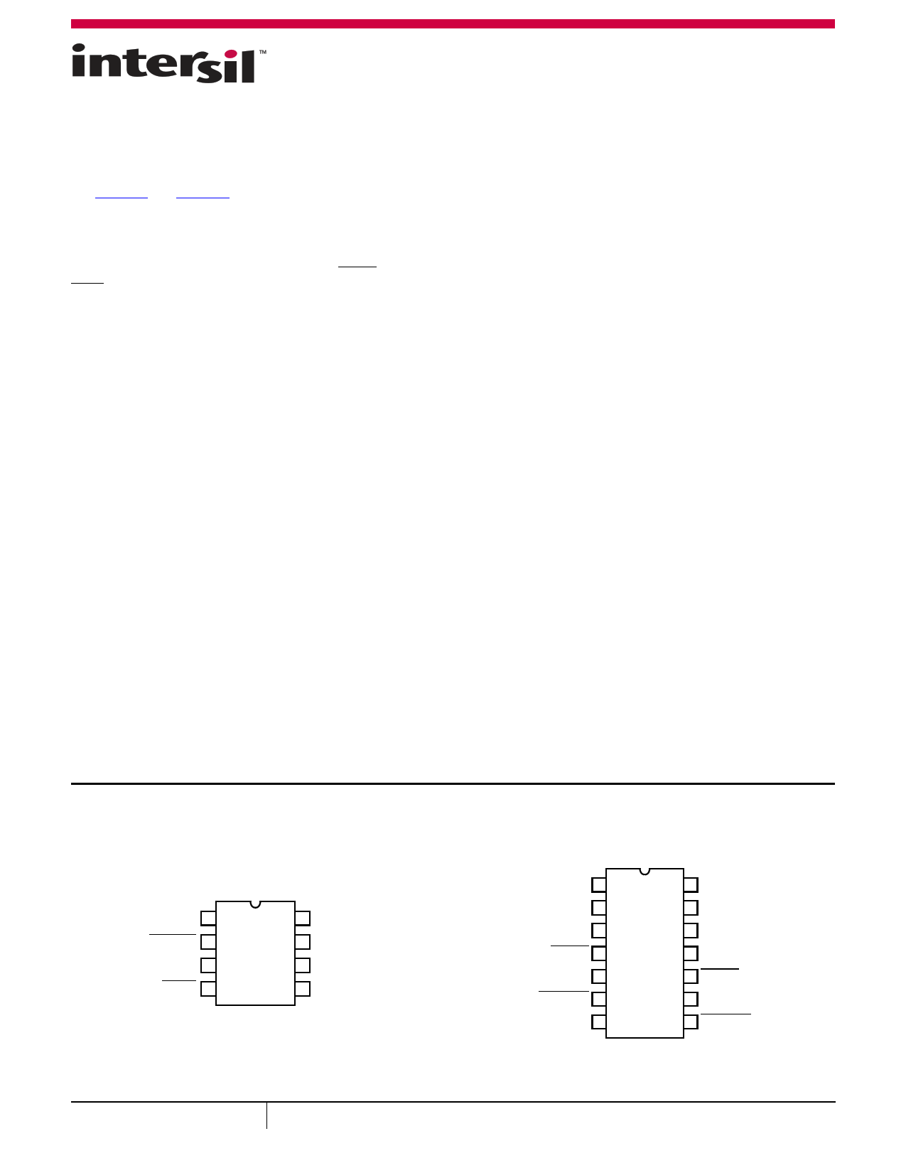
Pin Configurations
ICM7555
(8 LD PDIP, SOIC)
TOP VIEW
GND 1
TRIGGER 2
OUTPUT 3
RESET 4
8 VDD
7 DISCHARGE
6 THRESHOLD
5
CONTROL
VOLTAGE
Features
• Exact equivalent in most cases for SE/NE 555/556 or
TLC555/556
• Low supply current
- ICM7555 . . . . . . . . . . . . . . . . . . . . . . . . . . . . . . . . . . . . . 60µA
- ICM7556 . . . . . . . . . . . . . . . . . . . . . . . . . . . . . . . . . . . 120µA
• Extremely low input currents . . . . . . . . . . . . . . . . . . . . . . 20pA
• High speed operation . . . . . . . . . . . . . . . . . . . . . . . . . . . . 1MHz
• Guaranteed supply voltage range . . . . . . . . . . . . . . 2V to 18V
• Temperature stability . . . . . . . . . . . . . 0.005%/°C at +25°C
• Normal reset function - no crowbarring of supply during
output transition
• Can be used with higher impedance timing elements than
regular 555/556 for longer RC time constants
• Timing from microseconds through hours
• Operates in both astable and monostable modes
• Adjustable duty cycle
• High output source/sink driver can drive TTL/CMOS
• Outputs have very low offsets, HIGH and LOW
• Pb-free (RoHS Compliant)
Applications
• Precision timing
• Pulse generation
• Sequential timing
• Time delay generation
• Pulse width modulation
• Pulse position modulation
• Missing pulse detector
ICM7556
(14 LD PDIP, CERDIP)
TOP VIEW
DISCHARGE1 1
THRESHOLD1 2
CONTROL
VOLTAGE1
3
RESET1 4
OUTPUT1 5
TRIGGER1 6
GND 7
14 VDD
13 DISCHARGE2
12 THRESHOLD2
11
CONTROL
VOLTAGE2
10 RESET2
9 OUTPUT2
8 TRIGGER2
June 28, 2016
FN2867.10
1 CAUTION: These devices are sensitive to electrostatic discharge; follow proper IC Handling Procedures.
1-888-INTERSIL or 1-888-468-3774 | Copyright Intersil Americas LLC 2002, 2004-2006, 2016. All Rights Reserved
Intersil (and design) is a trademark owned by Intersil Corporation or one of its subsidiaries.
All other trademarks mentioned are the property of their respective owners.
1 page 
Schematic Diagram
PP
ICM7555, ICM7556
P
R
VDD
P
THRESHOLD
CONTROL
VOLTAGE
N
TRIGGER
N
R
P
P
NPN
OUTPUT
R
N
NN N N
NN
R = 100kΩ ±20% (TYP)
RESET
FIGURE 2. SCHEMATIC DIAGRAM
DISCHARGE
GND
Application Information
General
The ICM7555 and ICM7556 devices are, in most instances,
direct replacements for the SE/NE 555/556 devices. However,
it is possible to effect economies in the external component
count using the ICM7555 and ICM7556. Because the bipolar
SE/NE 555/556 devices produce large crowbar currents in the
output driver, it is necessary to decouple the power supply
lines with a good capacitor close to the device. The ICM7555
and ICM7556 devices produce no such transients (see
Figure 3).
500
TA = +25°C
400
300
SE/NE 555
200
100
0
ICM7555/556
0 200 400 600 800
TIME (ns)
FIGURE 3. SUPPLY CURRENT TRANSIENT COMPARED WITH A
STANDARD BIPOLAR 555 DURING AN OUTPUT
TRANSITION
The ICM7555 and ICM7556 produce supply current spikes of
only 2mA to 3mA instead of 300mA to 400mA and supply
decoupling is normally not necessary. Also, in most instances,
the Control Voltage decoupling capacitors are not required
since the input impedance of the CMOS comparators on chip
are very high. Thus, for many applications, two capacitors can
be saved using an ICM7555 and three capacitors with an
ICM7556.
POWER SUPPLY CONSIDERATIONS
Although the supply current consumed by the ICM7555 and
ICM7556 devices is very low, the total system supply current
can be high unless the timing components are high
impedance. Therefore, use high values for R and low values for
C in Figures 4, 5, and 6.
GND
1
TRIGGER
2
VDD
3
4
RESET
R
VDD
VDD
8
DISCHARGE
7
10k
THRESHOLD
6
5
CONTROL
VOLTAGE
C
OPTIONAL
CAPACITOR
FIGURE 4. ASTABLE OPERATION
Submit Document Feedback
5
FN2867.10
June 28, 2016
5 Page 
ICM7555, ICM7556
Dual-In-Line Plastic Packages (PDIP)
INDEX
AREA
N
12 3
-A-
BASE
PLANE
SEATING
PLANE
D1
B1
B
E1
N/2
-B-
D
-C- A2 A
L
e D1
A1
eC
0.010 (0.25) M C A B S
E
CL
eA
C
eB
NOTES:
1. Controlling Dimensions: INCH. In case of conflict between English
and Metric dimensions, the inch dimensions control.
2. Dimensioning and tolerancing per ANSI Y14.5M-1982.
3. Symbols are defined in the “MO Series Symbol List” in Section 2.2
of Publication No. 95.
4. Dimensions A, A1 and L are measured with the package seated in
JEDEC seating plane gauge GS-3.
5. D, D1, and E1 dimensions do not include mold flash or protrusions.
Mold flash or protrusions shall not exceed 0.010 inch (0.25mm).
6. E and eA are measured with the leads constrained to be
perpendicular to datum -C- .
7. eB and eC are measured at the lead tips with the leads
unconstrained. eC must be zero or greater.
8. B1 maximum dimensions do not include dambar protrusions.
Dambar protrusions shall not exceed 0.010 inch (0.25mm).
9. N is the maximum number of terminal positions.
10. Corner leads (1, N, N/2 and N/2 + 1) for E8.3, E16.3, E18.3, E28.3,
E42.6 will have a B1 dimension of 0.030 - 0.045 inch (0.76 -
1.14mm).
E8.3 (JEDEC MS-001-BA ISSUE D)
8 LEAD DUAL-IN-LINE PLASTIC PACKAGE
INCHES
MILLIMETERS
SYMBOL MIN MAX MIN MAX NOTES
A
-
0.210
-
5.33 4
A1 0.015 -
0.39
-
4
A2
0.115 0.195 2.93
4.95
-
B
0.014 0.022 0.356 0.558
-
B1
0.045 0.070 1.15
1.77 8, 10
C
0.008 0.014 0.204 0.355
-
D
0.355 0.400 9.01 10.16
5
D1 0.005 -
0.13
-
5
E
0.300 0.325 7.62
8.25
6
E1
0.240 0.280 6.10
7.11
5
e 0.100 BSC
2.54 BSC
-
eA 0.300 BSC
7.62 BSC
6
eB
-
0.430
- 10.92
7
L
0.115 0.150 2.93
3.81
4
N8
89
Rev. 0 12/93
Submit Document Feedback 11
FN2867.10
June 28, 2016
11 Page | ||
| Páginas | Total 13 Páginas | |
| PDF Descargar | [ Datasheet ICM7555.PDF ] | |
Hoja de datos destacado
| Número de pieza | Descripción | Fabricantes |
| ICM7555 | General Purpose Timers | Intersil Corporation |
| ICM7555 | General purpose CMOS timer | NXP Semiconductors |
| ICM7555 | General Purpose timers | Maxim Integrated |
| ICM7555 | General purpose CMOS timer | Philips |
| Número de pieza | Descripción | Fabricantes |
| SLA6805M | High Voltage 3 phase Motor Driver IC. |
Sanken |
| SDC1742 | 12- and 14-Bit Hybrid Synchro / Resolver-to-Digital Converters. |
Analog Devices |
|
DataSheet.es es una pagina web que funciona como un repositorio de manuales o hoja de datos de muchos de los productos más populares, |
| DataSheet.es | 2020 | Privacy Policy | Contacto | Buscar |