|
|
|
PDF MAX1614EUA Data sheet ( Hoja de datos )
| Número de pieza | MAX1614EUA | |
| Descripción | High-Side / N-Channel MOSFET Switch Driver | |
| Fabricantes | Maxim Integrated | |
| Logotipo | ||
Hay una vista previa y un enlace de descarga de MAX1614EUA (archivo pdf) en la parte inferior de esta página. Total 8 Páginas | ||
|
No Preview Available !
19-1176; Rev 0; 12/96
High-Side, N-Channel MOSFET
Switch Driver
_______________General Description
The MAX1614 drives high-side, N-channel power MOSFETs
to provide battery power-switching functions in portable
equipment. N-channel power MOSFETs typically have
one-third the on-resistance of P-channel MOSFETs of simi-
lar size and cost. An internal micropower regulator and
charge pump generate the high-side drive output voltage,
while requiring no external components.
The MAX1614 also features a 1.5%-accurate low-battery
comparator that can be used to indicate a low-battery
condition, provide an early power-fail warning to the sys-
tem microprocessor, or disconnect the battery from the
load, preventing deep discharge and battery damage. An
internal latch allows for pushbutton on/off control with very
low current consumption. Off-mode current consumption
is only 6µA while normal operation requires less than
25µA. The MAX1614 is available in the space-saving
µMAX package that occupies about 60% less space than
a standard 8-pin SO.
________________________Applications
Notebook Computers
Portable Equipment
Hand-Held Instruments
Battery Packs
____________________________Features
o Internal On/Off Latch
o High-Side, N-Channel Power MOSFET Drive
o 25µA (max) Quiescent Current
o 6µA (max) Off Current
o Requires No External Components
o 1.5%-Accurate Low-Battery Detector
o Space-Saving µMAX Package
o 5V to 26V Input Voltage Range
o Drives Single or Back-to-Back MOSFETs
o Controlled Turn-On for Low Inrush Current
______________Ordering Information
PART
TEMP. RANGE
MAX1614C/D
0°C to +70°C
MAX1614EUA -40°C to +85°C
*Contact factory for dice specifications.
PIN-PACKAGE
Dice*
8 µMAX
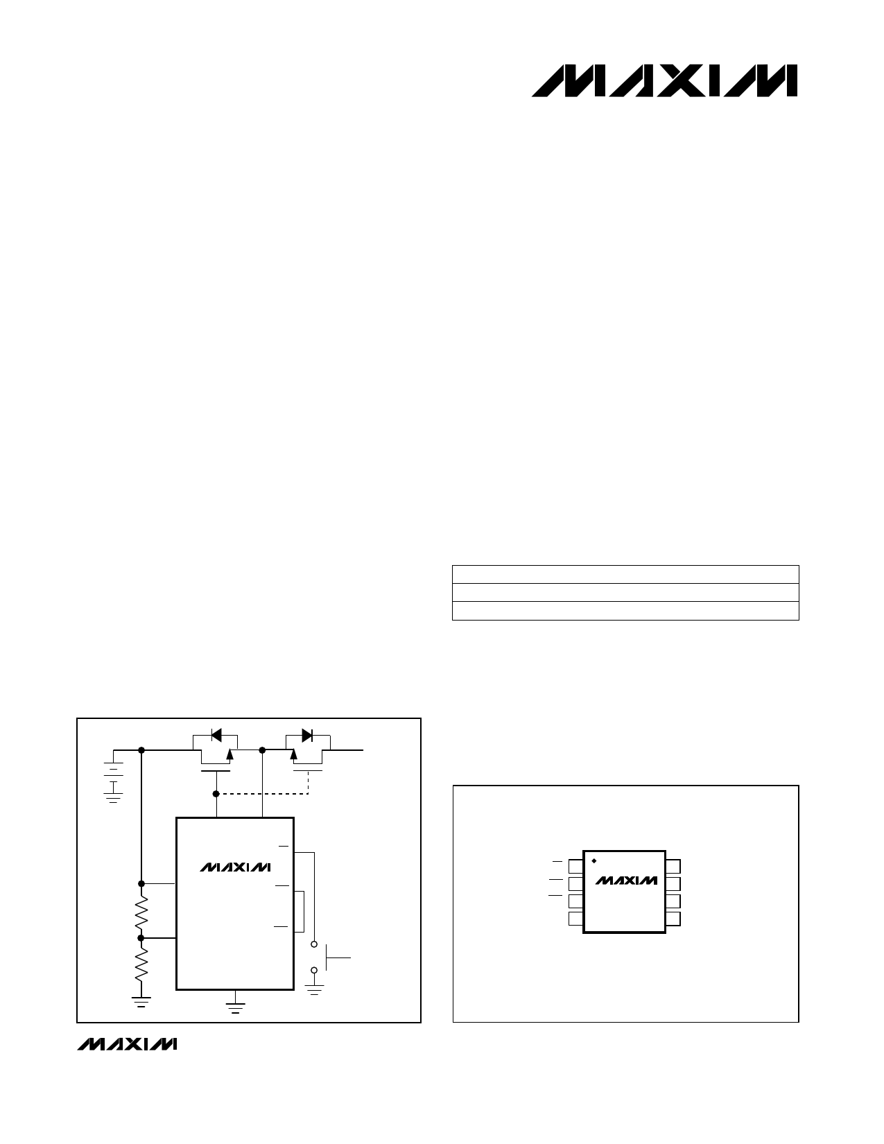
__________Typical Operating Circuit
N N LOAD
GATE SRC
ON
OPTIONAL FOR
REVERSE CURRENT
PROTECTION
BATT MAX1614 OFF
R1
LBI LBO
R2
GND
__________________Pin Configuration
TOP VIEW
ON 1
OFF 2
LBO 3
LBI 4
MAX1614
µMAX
8 BATT
7 SRC
6 GATE
5 GND
________________________________________________________________ Maxim Integrated Products 1
For free samples & the latest literature: http://www.maxim-ic.com, or phone 1-800-998-8800
1 page 
High-Side, N-Channel MOSFET
Switch Driver
______________________________________________________________Pin Description
PIN NAME
FUNCTION
1
ON
SET Input to the On/Off Latch. Pulse ON low with OFF high to turn on the external MOSFET switch. When
both ON and OFF are low, the part is off.
2
OFF
RESET Input to the On/Off Latch. Pulse OFF low with ON high to turn off the external MOSFET switch. When
both ON and OFF are low, the part is off.
3
LBO
Open-Drain, Low-Battery Comparator Output. LBO is low when VLBI is below the trip point.
4
LBI
Low-Battery Comparator Input. LBO goes low when VLBI falls below 1.20V (typ). Connect a voltage divider
between BATT, LBI, and GND to set the battery undervoltage trip threshold (see Typical Operating Circuit).
5 GND System Ground
6
GATE
Gate-Drive Output. Connect to the gates of external, N-channel MOSFETs. When the MAX1614 is off, GATE
actively pulls to GND.
7
SRC
Source Input. Connect to the sources of external, N-channel MOSFETs. When the MAX1614 is off, SRC
actively pulls to GND.
8 BATT Battery Input. Connect to a battery voltage between 5V and 26V.
_______________Detailed Description
The MAX1614 uses an internal, monolithic charge pump
and low-dropout linear regulator to supply the required
8V VGS voltage to fully enhance an N-channel MOSFET
high-side switch (Figure 1). The charge pump typically
supplies 30µA, charging 800pF of gate capacitance in
400µs (VBATT = 15V). For slower turn-on times, simply
add a small capacitor between the GATE and SRC
pins. When turned off, GATE and SRC pull low and typi-
cally discharge an 800pF gate capacitance in 80µs.
The MAX1614 provides separate on/off control inputs
(ON and OFF). ON and OFF connect, respectively, to
the SET and RESET inputs of an internal flip-flop. When
ON is pulsed low (with OFF = high), the internal charge
pump turns on, and GATE is pumped to 8V above SRC,
turning on the external MOSFETs. The charge pump
maintains gate drive to the external MOSFETs until OFF
is pulsed low. When this happens, the internal charge
pump turns off, and GATE discharges to ground
through an internal switch. For slower turn-on times,
simply add a small capacitor.
__________ Applications Information
Connecting ON/OFF to 3V or 5V Logic
ON and OFF internally connect to 2µA max pull-up
current sources (Figure 1). The open-circuit voltage
for ON and OFF ranges from 7V to 10.5V (nominally
8.5V). Since the current sources are relatively weak,
connecting ON and OFF directly to logic powered from
lower voltages (e.g., 3V or 5V) poses no problem if the
gate outputs driving these pins can sink at least 2µA
while high.
Although the MAX1614 shutdown function was designed
to operate with a single pushbutton on/off switch, it can
also be driven by a single gate. Connect ON to GND
and drive OFF directly (Figure 2).
Maximum Switching Rate
The MAX1614 is not intended for fast switching appli-
cations. In fact, it is specifically designed to limit the
rate of change of the load current, ∆I/∆t. The maximum
switching rate is limited by the turn-on time, which is a
function of the charge-pump output current and the
total capacitance on GATE (CGATE). Calculate the turn-
on time as a function of external MOSFET gate capaci-
tance using the Gate Charging Current vs. VBATT graph
in the Typical Operating Characteristics. Since turn-off
time is small compared to turn-on time, the maximum
switching rate is approximately 1/tON.
Adding Gate Capacitance
The charge pump uses an internal monolithic transfer
capacitor to charge the external MOSFET gates.
Normally, the external MOSFET’s gate capacitance is
sufficient to serve as a reservoir capacitor. If the
MOSFETs are located at a significant distance from the
MAX1614, place a local bypass capacitor (100pF typ)
across the GATE and SRC pins. For slower turn-on
times, simply add a small capacitor between GATE and
SRC.
_______________________________________________________________________________________ 5
5 Page | ||
| Páginas | Total 8 Páginas | |
| PDF Descargar | [ Datasheet MAX1614EUA.PDF ] | |
Hoja de datos destacado
| Número de pieza | Descripción | Fabricantes |
| MAX1614EUA | High-Side / N-Channel MOSFET Switch Driver | Maxim Integrated |
| Número de pieza | Descripción | Fabricantes |
| SLA6805M | High Voltage 3 phase Motor Driver IC. |
Sanken |
| SDC1742 | 12- and 14-Bit Hybrid Synchro / Resolver-to-Digital Converters. |
Analog Devices |
|
DataSheet.es es una pagina web que funciona como un repositorio de manuales o hoja de datos de muchos de los productos más populares, |
| DataSheet.es | 2020 | Privacy Policy | Contacto | Buscar |