|
|
|
PDF 99026 Data sheet ( Hoja de datos )
| Número de pieza | 99026 | |
| Descripción | HALF BRIDGE DRIVER Evaluation Board | |
| Fabricantes | IXYS Corporation | |
| Logotipo | ||
Hay una vista previa y un enlace de descarga de 99026 (archivo pdf) en la parte inferior de esta página. Total 8 Páginas | ||
|
No Preview Available !
EVBD4400
HALF BRIDGE DRIVER Evaluation Board
Features
• High to low side isolation of 1000V
• Common-mode dv/dt immunity of greater than
50V/nanosecond
• On-chip generated negative gate drive
• Overcurrent protection by means of desaturation
detection
• Under voltage lockout
• Fault indication output for system diagnostic
• Optimized power circuit layout
• High side bootstrap supply
• Sockets for freewheeling fast recovery diodes
(FREDS)
• Flexibility of power level utilization
• 5V compatible HCMOS input logic with hysterisis
• Protection from cross conduction of the half
bridge
• Simple, fast and low cost means of evaluation
and design
• Option for using IXDP630 with RC oscillator or
IXDP631 with crystal oscillator for improved dead
time accuracy.
• Three phase operation with the ability to attach
additional slave driver boards.
Introduction
The EVBD4400 evaluation board implements a single
power phaseleg circuit on a double sided PCB with
ground plane, using the proven ISOSMARTTM HALF
BRIDGE DRIVER CHIPSET - IXBD4410, IXBD4411,
IXDP630. The IXDP631 is optional. This board includes
all parts required for the circuit implementation so that
you can just follow the instructions in this document and
connect the board to the load and power. The kit
consists of an assembled and tested PCB with two
power devices.
Any power circuit is layout sensitive. The layout of this kit
is a proven, working layout. The designer is invited to
duplicate this layout in his system, following the evaluation
of the driver chipset.
Most systems vary in their power level requirements and
therefore the power devices used. Due to this fact and
fluctuations in availability of power devices, the kit will not
always include the same power devices. The designer is
encouraged to use the power devices that are required for
his system. The devices that are enclosed serve only for
initial evaluation.
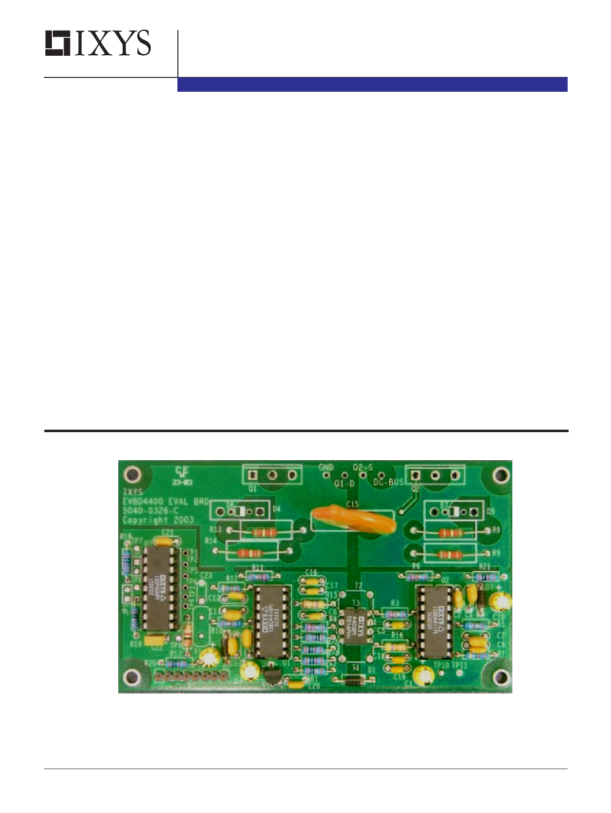
Figure 1: EVBD4400 Assembled PC board
Copyright © IXYS CORPORATION 2003
First Release
DS99026A(07/03)
1 page 
EVBD4400
OPERATION:
For performance evaluation and power
system design please note the following:
a) The assembled board can be ran with the
IXDP630/631 removed by applying comple-
mentary 5V square waves with proper "dead
time" to the input pins INL (P1-3) and INH (P1-
2).
For standard IXDP630 operation, R17
and C22 have been loaded with their respec-
tive values represented on the bill of materi-
als. These values are for demonstration and
may not be appropriate for your application.
Change values as needed. For IXDP631
operation, load R17, C22, C23 with the rec-
ommended load components as outlined in
the IXDP630/631 data sheet along with the
crystal at the frequency of choice. R17 and
C22 serve a dual purpose depending on
which dead timer is selected.
The IXDP630 is hardwired for phase
'R' operation, see 630/631 data sheet, with
pins OUTENA, ENAR, and RESET tied high.
PWM drive input signal for ' R' phase is
applied to P1-6.
To add phases 'S' and / or 'T', enable
phases with jumpers at JP1 and/or JP2 and
apply PWM phase drive signals to TP7 and/
or TP8 taking the respective complementary
outputs from TP3 through TP6. Note that
TP1-TP15 are through-hole pads that have
been added to the board to serve as conve-
nient solder and / or test points.
If additional 'slave' boards are to be
used for mutiple phase operation, R17 -
R19, C20 - C23, and Y1 do not need to be
installed on the addtional slave boards.
b) Be careful with ground connections.
Avoid ground loops. In general, connect the
grounds as shown in Figure 4 to minimize
ground bounce effects. This is particularly
important when three "High/Low side driver
design kits" are connected together with a
single IXDP630 to form a three phase drive
system, such as that shown in Figure 5.
c) Before using the PCB at full power or at-
tempting a short circuit test, make sure that a
proper high voltage electroytic capacitor is
connected between DC BUS and GND as
shown in Figure 4. The leads to this capacitor
should be as short as possible to minimize any
stray inductance.
d) Figure 4 shows the load terminated at point
A. This point could be connected to a number of
places depending on the application. For ex-
ample: Connection to ground will test the high
side device. Connection to DC BUS will test the
low side device. It could also be connected to
the center point of a capacitive divider (UPS
systems).
e) Figure 5 shows a three phase power system
implementation with a load configured in a Y
(star). It could also be configured in a DELTA
configuration. Please note the grounding
scheme. Cut the connection between "ground
plane 2" and "ground plane 4" on the compo-
nents side of the PCB and solder a 10 Ohm
resistor between these ground planes. The GND
of each board is terminated to a single ground
point.
5
5 Page | ||
| Páginas | Total 8 Páginas | |
| PDF Descargar | [ Datasheet 99026.PDF ] | |
Hoja de datos destacado
| Número de pieza | Descripción | Fabricantes |
| 99026 | HALF BRIDGE DRIVER Evaluation Board | IXYS Corporation |
| Número de pieza | Descripción | Fabricantes |
| SLA6805M | High Voltage 3 phase Motor Driver IC. |
Sanken |
| SDC1742 | 12- and 14-Bit Hybrid Synchro / Resolver-to-Digital Converters. |
Analog Devices |
|
DataSheet.es es una pagina web que funciona como un repositorio de manuales o hoja de datos de muchos de los productos más populares, |
| DataSheet.es | 2020 | Privacy Policy | Contacto | Buscar |