|
|
|
PDF LM13700A Data sheet ( Hoja de datos )
| Número de pieza | LM13700A | |
| Descripción | Dual Operational Transconductance Amplifiers | |
| Fabricantes | National Semiconductor | |
| Logotipo | ||
Hay una vista previa y un enlace de descarga de LM13700A (archivo pdf) en la parte inferior de esta página. Total 24 Páginas | ||
|
No Preview Available !
May 1998
LM13700/LM13700A
Dual Operational Transconductance Amplifiers with
Linearizing Diodes and Buffers
General Description
The LM13700 series consists of two current controlled
transconductance amplifiers, each with differential inputs
and a push-pull output. The two amplifiers share common
supplies but otherwise operate independently. Linearizing di-
odes are provided at the inputs to reduce distortion and allow
higher input levels. The result is a 10 dB signal-to-noise im-
provement referenced to 0.5 percent THD. High impedance
buffers are provided which are especially designed to
complement the dynamic range of the amplifiers. The output
buffers of the LM13700 differ from those of the LM13600 in
that their input bias currents (and hence their output DC lev-
els) are independent of IABC. This may result in performance
superior to that of the LM13600 in audio applications.
Features
n gm adjustable over 6 decades
n Excellent gm linearity
n Excellent matching between amplifiers
n Linearizing diodes
n High impedance buffers
n High output signal-to-noise ratio
Applications
n Current-controlled amplifiers
n Current-controlled impedances
n Current-controlled filters
n Current-controlled oscillators
n Multiplexers
n Timers
n Sample-and-hold circuits
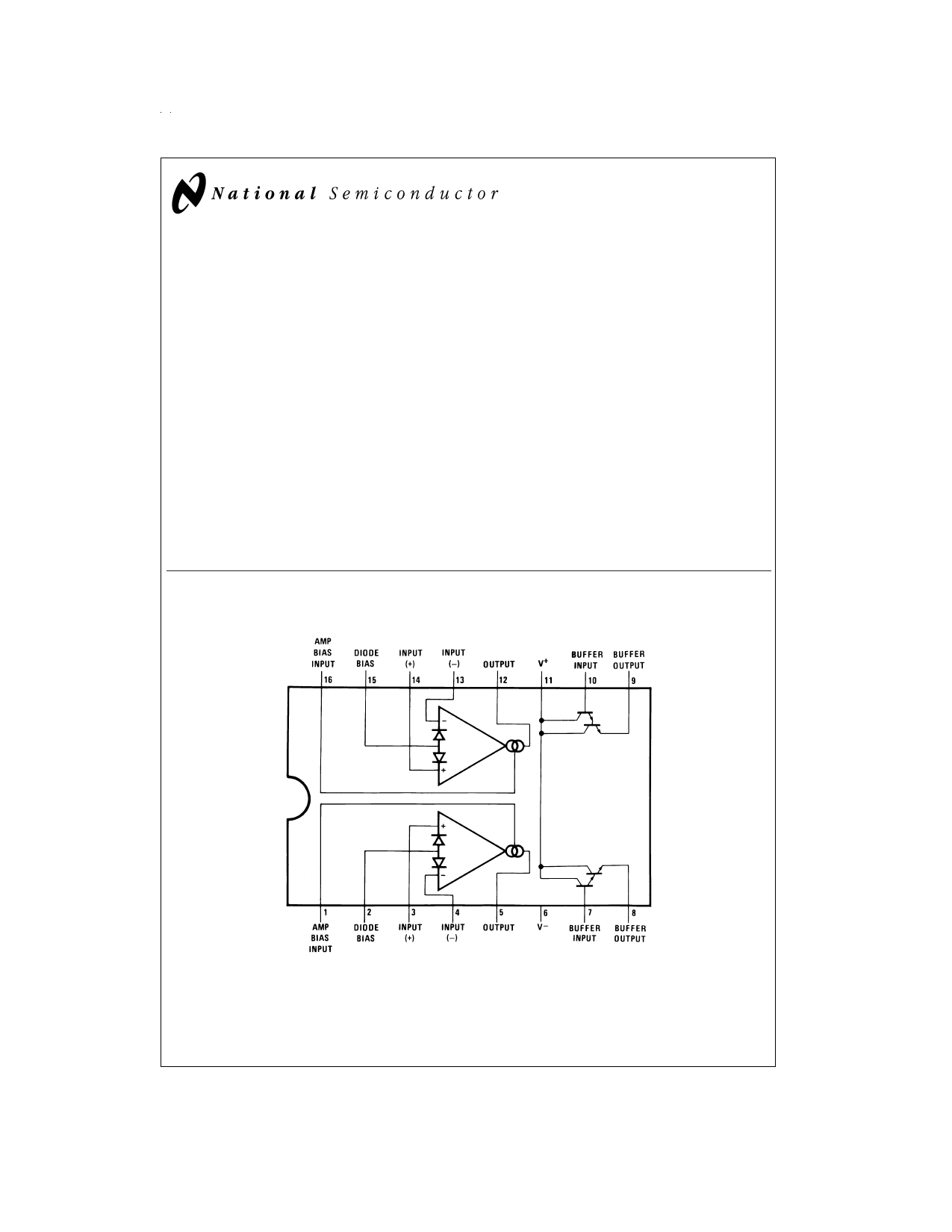
Connection Diagram
Dual-In-Line and Small Outline Packages
DS007981-2
Top View
Order Number LM13700M, LM13700N or LM13700AN
See NS Package Number M16A or N16A
© 1999 National Semiconductor Corporation DS007981
www.national.com
1 page 
Typical Performance Characteristics (Continued)
Distortion vs Differential
Input Voltage
Voltage vs Amplifier
Bias Current
Output Noise vs Frequency
DS007981-50
DS007981-51
Unity Gain Follower
DS007981-52
Leakage Current Test Circuit
DS007981-5
Differential Input Current Test Circuit
DS007981-6
Circuit Description
The differential transistor pair Q4 and Q5 form a transcon-
ductance stage in that the ratio of their collector currents is
defined by the differential input voltage according to the
transfer function:
DS007981-7
(1)
where VIN is the differential input voltage, kT/q is approxi-
mately 26 mV at 25˚C and I5 and I4 are the collector currents
of transistors Q5 and Q4 respectively. With the exception of
5 www.national.com
5 Page 
Voltage Controlled Filters (Continued)
FIGURE 10. Floating Voltage Controlled Resistor
DS007981-17
FIGURE 11. Voltage Controlled Low-Pass Filter
DS007981-18
11 www.national.com
11 Page | ||
| Páginas | Total 24 Páginas | |
| PDF Descargar | [ Datasheet LM13700A.PDF ] | |
Hoja de datos destacado
| Número de pieza | Descripción | Fabricantes |
| LM13700 | Dual Operational Transconductance Amplifiers with Linearizing Diodes and Buffers | National Semiconductor |
| LM13700 | LM13700 Dual Operational Transconductance Amps w/Linearizing Diodes and Buffers (Rev. F) | Texas Instruments |
| LM13700A | Dual Operational Transconductance Amplifiers | National Semiconductor |
| Número de pieza | Descripción | Fabricantes |
| SLA6805M | High Voltage 3 phase Motor Driver IC. |
Sanken |
| SDC1742 | 12- and 14-Bit Hybrid Synchro / Resolver-to-Digital Converters. |
Analog Devices |
|
DataSheet.es es una pagina web que funciona como un repositorio de manuales o hoja de datos de muchos de los productos más populares, |
| DataSheet.es | 2020 | Privacy Policy | Contacto | Buscar |