|
|
|
PDF 813N252I-09 Data sheet ( Hoja de datos )
| Número de pieza | 813N252I-09 | |
| Descripción | VCXO Jitter Attenuator & FemtoClock Multiplier | |
| Fabricantes | IDT | |
| Logotipo | ||
Hay una vista previa y un enlace de descarga de 813N252I-09 (archivo pdf) en la parte inferior de esta página. Total 23 Páginas | ||
|
No Preview Available !
VCXO Jitter Attenuator &
FemtoClock® Multiplier
813N252I-09
Datasheet
General Description
The 813N252I-09 is a PLL based synchronous multiplier that is
optimized for PDH or SONET to Ethernet clock jitter attenuation and
frequency translation. The device contains two internal frequency
multiplication stages that are cascaded in series. The first stage is a
VCXO PLL that is optimized to provide reference clock jitter
attenuation. The second stage is a FemtoClock™frequency multiplier
that provides the low jitter, high frequency Ethernet output clock that
easily meets Gigabit and 10 Gigabit Ethernet jitter requirements.
Pre-divider and output divider multiplication ratios are selected using
device selection control pins. The multiplication ratios are optimized
to support most common clock rates used in PDH, SONET and
Ethernet applications. The VCXO requires the use of an external,
inexpensive pullable crystal. The VCXO uses external passive loop
filter components which allows configuration of the PLL loop
bandwidth and damping characteristics. The device is packaged in a
space-saving 32-VFQFN package and supports industrial
temperature range.
Features
• Two LVPECL output pairs
Each output supports independent frequency selection at 25MHz,
125MHz, 156.25MHz and 312.5MHz
• Two differential inputs support the following input types: LVPECL,
LVDS, LVHSTL, SSTL, HCSL
• Accepts input frequencies from 8kHz to 155.52MHz including
8kHz, 1.544MHz, 2.048MHz, 19.44MHz, 25MHz, 77.76MHz,
125MHz and 155.52MHz
• Attenuates the phase jitter of the input clock by using a low-cost
pullable fundamental mode VCXO crystal
• VCXO PLL bandwidth can be optimized for jitter attenuation and
reference tracking using external loop filter connection
• FemtoClock frequency multiplier provides low jitter, high frequency
output
• Absolute pull range: 50ppm
• FemtoClock VCO frequency: 625MHz
• RMS phase jitter @ 125MHz, using a 25MHz crystal
(12kHz – 20MHz): 0.25ps (typical) and 0.35ps (maximum)
• 3.3V supply voltage
• -40°C to 85°C ambient operating temperature
• Available in lead-free (RoHS 6) package
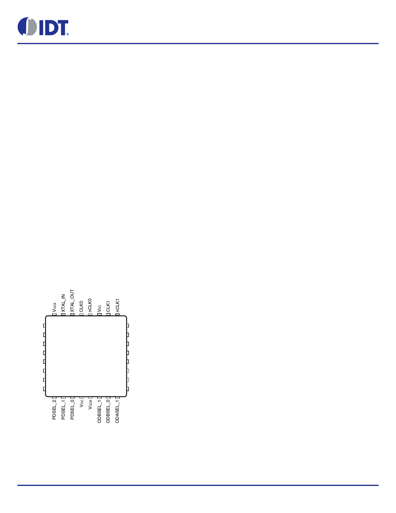
Pin Assignment
32 31 30 29 28 27 26 25
LF1 1
24 VEE
LF0 2
23 nQB
ISET 3
22 QB
VEE 4
21 VCCO
CLK_SEL 5
20 nQA
VCC 6
19 QA
RESERVED 7
18 VEE
VEE 8
17 ODASEL_0
9 10 11 12 13 14 15 16
813N252I-09
32 Lead VFQFN
5mm x 5mm x 0.925mm package body
3.15mm x 3.15mm EPad
K Package
Top View
©2015 Integrated Device Technology, Inc.
1
Revision C, December 10, 2015
1 page 
813N252I-09 Datasheet
Table 3C. Frequency Function Table
Input
Frequency
(MHz)
Pre-Divider VCXO Frequency
Value
(MHz)
0.008
1
25
0.008
1
25
0.008
1
25
0.008
1
25
1.544
193
25
1.544
193
25
1.544
193
25
1.544
193
25
2.048
256
25
2.048
256
25
2.048
256
25
2.048
256
25
19.44
2430
25
19.44
2430
25
19.44
2430
25
19.44
2430
25
25 3125
25
25 3125
25
25 3125
25
25 3125
25
77.76
9720
25
77.76
9720
25
77.76
9720
25
77.76
9720
25
125 15625
25
125 15625
25
125 15625
25
125 15625
25
155.52
19440
25
155.52
19440
25
155.52
19440
25
155.52
19440
25
FemtoClock
Feedback
Divider Value
25
25
25
25
25
25
25
25
25
25
25
25
25
25
25
25
25
25
25
25
25
25
25
25
25
25
25
25
25
25
25
25
FemtoClock VCO
Frequency (MHz)
625
625
625
625
625
625
625
625
625
625
625
625
625
625
625
625
625
625
625
625
625
625
625
625
625
625
625
625
625
625
625
625
Output Divider
Value
25
5
4
2
25
5
4
2
25
5
4
2
25
5
4
2
25
5
4
2
25
5
4
2
25
5
4
2
25
5
4
2
Output Frequency
(MHz)
25
125
156.25
312.5
25
125
156.25
312.5
25
125
156.25
312.5
25
125
156.25
312.5
25
125
156.25
312.5
25
125
156.25
312.5
25
125
156.25
312.5
25
125
156.25
312.5
©2015 Integrated Device Technology, Inc.
5
Revision C, December 10, 2015
5 Page 
813N252I-09 Datasheet
Wiring the Differential Input to Accept Single-Ended Levels
Figure 2 shows how a differential input can be wired to accept single
ended levels. The reference voltage V1= VCC/2 is generated by the
bias resistors R1 and R2. The bypass capacitor (C1) is used to help
filter noise on the DC bias. This bias circuit should be located as close
to the input pin as possible. The ratio of R1 and R2 might need to be
adjusted to position the V1in the center of the input voltage swing. For
example, if the input clock swing is 2.5V and VCC = 3.3V, R1 and R2
value should be adjusted to set V1 at 1.25V. Similarly, if the input clock
swing is 1.8V and VCC = 3.3V, R1 and R2 value should be adjusted
to set V1 at 0.9V. It is recommended to always use R1 and R2 to
provide a known V1 voltage. The values below are for when both the
single ended swing and VCC are at the same voltage. This
configuration requires that the sum of the output impedance of the
driver (Ro) and the series resistance (Rs) equals the transmission
line impedance. In addition, matched termination at the input will
attenuate the signal in half. This can be done in one of two ways.
First, R3 and R4 in parallel should equal the transmission line
impedance. For most 50 applications, R3 and R4 can be 100. The
values of the resistors can be increased to reduce the loading for
slower and weaker LVCMOS driver. When using single-ended
signaling, the noise rejection benefits of differential signaling are
reduced. Even though the differential input can handle full rail
LVCMOS signaling, it is recommended that the amplitude be
reduced. The datasheet specifies a lower differential amplitude,
however this only applies to differential signals. For single-ended
applications, the swing can be larger, however VIL cannot be less
than -0.3V and VIH cannot be more than VCC + 0.3V. Though some
of the recommended components might not be used, the pads
should be placed in the layout. They can be utilized for debugging
purposes. The datasheet specifications are characterized and
guaranteed by using a differential signal.
Figure 2. Recommended Schematic for Wiring a Differential Input to Accept Single-ended Levels
©2015 Integrated Device Technology, Inc.
11
Revision C, December 10, 2015
11 Page | ||
| Páginas | Total 23 Páginas | |
| PDF Descargar | [ Datasheet 813N252I-09.PDF ] | |
Hoja de datos destacado
| Número de pieza | Descripción | Fabricantes |
| 813N252I-09 | VCXO Jitter Attenuator & FemtoClock Multiplier | IDT |
| Número de pieza | Descripción | Fabricantes |
| SLA6805M | High Voltage 3 phase Motor Driver IC. |
Sanken |
| SDC1742 | 12- and 14-Bit Hybrid Synchro / Resolver-to-Digital Converters. |
Analog Devices |
|
DataSheet.es es una pagina web que funciona como un repositorio de manuales o hoja de datos de muchos de los productos más populares, |
| DataSheet.es | 2020 | Privacy Policy | Contacto | Buscar |