|
|
|
PDF BM1P101FJ Data sheet ( Hoja de datos )
| Número de pieza | BM1P101FJ | |
| Descripción | DC/DC converter IC | |
| Fabricantes | ROHM Semiconductor | |
| Logotipo | ||
Hay una vista previa y un enlace de descarga de BM1P101FJ (archivo pdf) en la parte inferior de esta página. Total 21 Páginas | ||
|
No Preview Available !
Datasheet
AC/DC Drivers
PWM Control type
DC/DC converter IC
BM1P061FJ / BM1P062FJ / BM1P101FJ / BM1P102FJ
●General
The PWM type DC/DC converter (BM1Pxxx) for
AC/DC provide an optimum system for all products
that include an electrical outlet.
BM1Pxxx supports both isolated and non-isolated
devices, enabling simpler design of various types of
low-power electrical converters.
BM1Pxxx built in a HV starter circuit that tolerates
650V, it contributes to low-power consumption.
With switching MOSFET and current detection
resistors as external devices, a higher degree of
design freedom is achieved. Since current mode
control is utilized, current is restricted in each cycle
and excellent performance is demonstrated in
bandwidth and transient response.
At light load, the switching frequency is reduced and
high efficiency is achieved.
A frequency hopping function is also on chip, which
contributes to low EMI.
BM1Pxxx has rich protection.
●Basic specifications
Operating Power Supply Voltage Range:
VCC 8.9V to 26.0V
VH:
to 600V
Operating Current: Normal Mode:0.60mA (Typ.)
Burst Mode: 0.35mA(Typ.)
Oscillation Frequency: BM1P06xFJ:65kHz(Typ.)
BM1P10xFJ:100kHz(Typ.)
Operating Temperature:
- 40deg. to +85deg.
●Features
PWM frequency : 65kHz, 100kHz
PWM current mode method
Frequency Hopping function
Burst operation / Frequency reduction function
when load is light
Built-in 650V start circuit
VCC pin under voltage protection
VCC pin over voltage protection
CS pin Open protection
CS pin Leading-Edge-Blanking function
Per-cycle over current protection circuit
Current protection with AC voltage compensation
Soft start
Secondary Over current protection circuit
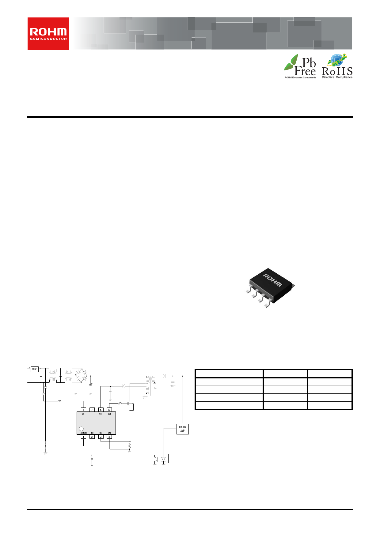
●Package
SOP-J8
4.90mm×3.90mm ×1.65mm
(Typ.) (Typ.) (TYP.)
Pitch 1.27mm
(TYP.)
●Applications
AC adapters and household appliances (vacuum
cleaners, humidifiers, air cleaners, air conditioners, IH
cooking heaters, rice cookers, etc.)
●Application circuit
●Line-Up
BM1P101FJ
BM1P102FJ
BM1P061FJ
BM1P062FJ
Frequency
100kHz
100kHz
65kHz
65kHz
VCCOVP
Auto Restart
Latch
Auto Restart
Latch
Figure 1.Application circuit
○Product structure:Silicon monolithic integrated circuit
.www.rohm.com
© 2012 ROHM Co., Ltd. All rights reserved.
TSZ22111・15・001
○This product is not designed protection against radioactive rays
1/18
TSZ02201-0F2F0A200090-1-2
22.NOV.2012.Rev.003
1 page 
BM1P061FJ / BM1P062FJ / BM1P101FJ / BM1P102FJ
●Block Diagram
Datasheet
Figure 3. Block Diagram
www.rohm.com
© 2012 ROHM Co., Ltd. All rights reserved.
TSZ22111・15・001
5/18
TSZ02201-0F2F0A200090-1-2
22.NOV.2012.Rev.003
5 Page 
BM1P061FJ / BM1P062FJ / BM1P101FJ / BM1P102FJ
Datasheet
(5) Over Current limiter
BM1Pxxx is built in the Over Current limiter per cycle. If the CS pin is over a certain voltage, the switching is stopped. It is
also built in the AC voltage compensation function. The function is rise over the current limiter level by time to compensate
AC voltage.
Shown in figure-12,13,14
Figure 12. No AC voltage compensation function
The primary peak current is decided as the formula below.
The primary peak current: Ipeak = Vcs/Rs + Vdc/Lp*Tdelay
Vcs :the over current limiter voltage
Rs :the current detection resistance
Vdc :the input DC voltage
Lp :the Primary inductance
Tdelay:the delay time after the detection of the over current limiter
Figure 13.buit-in AC compensation voltage
Figure 14. Over current limiter voltage
(6)L.E.B blanking period
When the driver MOSFET is turned ON, a surge current occurs at capacitor components and the drive current.
Therefore, because of rising the CS pin voltage temporarily, the detection errors may occur in the over current limiter
circuit. To prevent detection errors, when the OUT pin is switched from high to low, the CS signal is masked for 250 ns by
the on-chip LEB (Leading Edge Blanking) function. This blanking function reduces CS pin noise filter for the noise that
occurs when the OUT pin is switched from high to low.
www.rohm.com
© 2012 ROHM Co., Ltd. All rights reserved.
TSZ22111・15・001
11/18
TSZ02201-0F2F0A200090-1-2
22.NOV.2012.Rev.003
11 Page | ||
| Páginas | Total 21 Páginas | |
| PDF Descargar | [ Datasheet BM1P101FJ.PDF ] | |
Hoja de datos destacado
| Número de pieza | Descripción | Fabricantes |
| BM1P101FJ | DC/DC converter IC | ROHM Semiconductor |
| Número de pieza | Descripción | Fabricantes |
| SLA6805M | High Voltage 3 phase Motor Driver IC. |
Sanken |
| SDC1742 | 12- and 14-Bit Hybrid Synchro / Resolver-to-Digital Converters. |
Analog Devices |
|
DataSheet.es es una pagina web que funciona como un repositorio de manuales o hoja de datos de muchos de los productos más populares, |
| DataSheet.es | 2020 | Privacy Policy | Contacto | Buscar |