|
|
|
PDF CS8401A Data sheet ( Hoja de datos )
| Número de pieza | CS8401A | |
| Descripción | Digital Audio Interface Transmitter | |
| Fabricantes | Crystal Semiconductor | |
| Logotipo | ||
Hay una vista previa y un enlace de descarga de CS8401A (archivo pdf) en la parte inferior de esta página. Total 30 Páginas | ||
|
No Preview Available !
Semiconductor Corporation
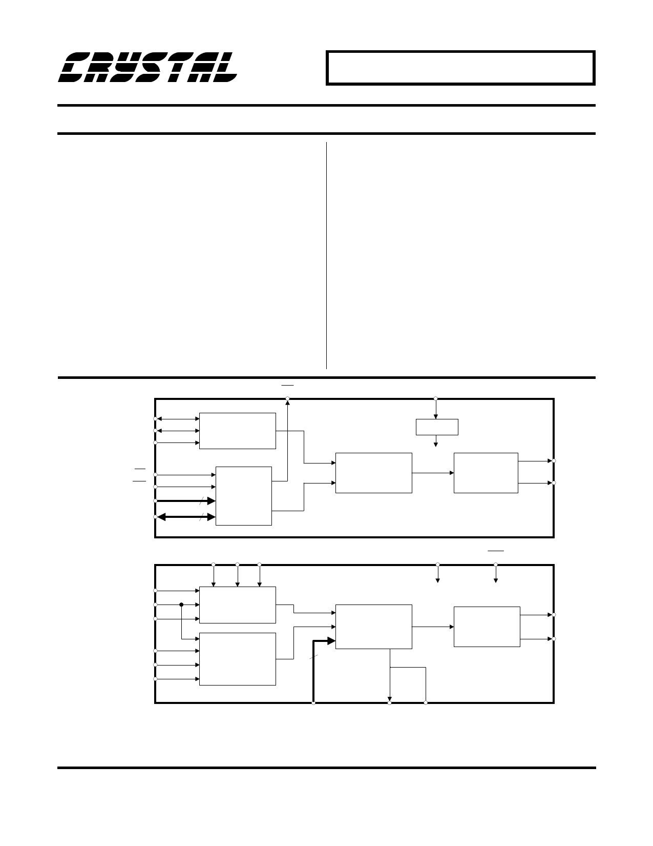
CS8401A CS8402A
Digital Audio Interface Transmitter
Features
General Description
• Monolithic Digital Audio Interface
The CS8401/2A are monolithic CMOS devices which
encode and transmit audio data according to the
Transmitter
AES/EBU, IEC 958, S/PDIF, & EIAJ CP-340 interface
• Supports: AES/EBU, IEC 958,
S/PDIF, & EIAJ CP-340
standards. The CS8401/2A accept audio and digital
data, which is then multiplexed, encoded and driven
onto a cable. The audio serial port is double buffered
Professional and Consumer Formats and capable of supporting a wide variety of formats.
• Host Mode and Stand Alone Modes
• Generates CRC Codes and Parity Bits
The CS8401A has a configurable internal buffer mem-
ory, loaded via a parallel port, which may be used to
buffer channel status, auxiliary data, and/or user data.
• On-Chip RS422 Line Driver
The CS8402A multiplexes the channel, user, and valid-
ity data directly from serial input pins with dedicated
• Configurable Buffer Memory (CS8401A) input pins for the most important channel status bits.
• Transparent Mode Allows Direct
Connection of CS8402A and CS8412
or CS8401A and CS8411A
ORDERING INFORMATION:
TABLE OF CONTENTS:
page 30
page 31
CS8401A
SCK
FSYNC
SDATA
6
7
8
Audio
Serial Port
INT
15
CS
RD/WR
14
16
Configurable
Buffer
A4 - A0
5 Memory
D7- D0
8
MUX
MCK
5
Prescaler
RS422 Driver
20 TXP
17
TXN
CS8402A
SCK
FSYNC
SDATA
6
7
8
C 10
U 11
V9
M2 M1 M0
23 22 21
Audio
Serial Port
Registers
MUX
7
MCK
5
RST
16
RS422 Driver
20 TXP
17 TXN
Dedicated Channel
Status Bits
15 24
CBL TRNPT
Crystal Semiconductor Corporation
P.O. Box 17847, Austin, TX 78760
(512) 445-7222 FAX: (512) 445-7581
NOV ’93
DS60F1
1
1 page 
CS8401A CS8402A
FSYNC
t sfds
SCK
SDATA
CS8402A
non-CD mode
CD mode
C,U,V
U
SBC
t sss
t css
t uss
t sfs t sckf
t ssh
t sch
t suh
Serial Input Timing - Master Mode & C, U, V Port
Audio
Data
Processor
Audio
Data
Processor
or
Micro-
controller
External
+5V Clock
5k
7
6
8
15
14
16
FSYNC
5
MCK
19
VD+
SCK
SDATA
18
GND
INT
CS8401A
CS
RD/WR
A0 - A4
20
TXP
D0 - D7
17
TXN
+5V
0.1 uF
Transmitter
Circuit
See Appendix B
Figure 1. CS8401A Typical Connection Diagram
DS60F1
5
5 Page 
CS8401A
SDF
210 (bit)
000
Name
MSB First
001 MSB Last
010 LSB Last 16
100 LSB Last 18
110 LSB Last 20
FSF MSTR
10 (bit)
00 0 FSYNC Input
01 0 FSYNC Input
10 0 FSYNC Input
11 0 FSYNC Input
Left Sample
MSB 24 bits, incl. Aux
LSB
Right Sample
MSB 24 bits, incl. Aux
LSB
MSB
MSB
LSB 24 bits, incl. Aux
MSB
LSB 24 bits, incl. Aux
MSB
16 Bits
16 Bits
LSB MSB LSB MSB LSB
18 Bits
18 Bits
LSB MSB LSB MSB LSB
20 Bits
20 Bits
LSB MSB
LSB MSB
LSB
00 1 FSYNC Output
01 1 FSYNC Output
10 1 FSYNC Output
11 1 FSYNC Output
16 Clocks
16 Clocks
32 Clocks
32 Clocks
16 Clocks
16 Clocks
32 Clocks
32 Clocks
Figure 10. CS8401A Serial Port SDATA and FSYNC Timing
MSB last mode, or by restricting the number of
SCK periods between samples to the sample
word length. The 16-, 18-, and 20-bit LSB-last
modes require at least 16, 18, or 20 SCK periods
per sample respectively. As a master, 32 SCK pe-
riods are output per sample.
FSYNC must be derived from MCK via a DSP
using the same clock or by external counters. If
FSYNC moves (jitters) with respect to MCK by
more than 4 MCK periods, the CS8401A may
reset the channel status block and flags. Appen-
dix C contains more information on the
relationship of FSYNC and MCK.
Buffer Memory
In all buffer modes, the status register and con-
trol registers are located at addresses 0-3
respectively, and the user data is buffered in lo-
cations 4-7. The parallel port can access any
location in the user data buffer at any time; how-
ever, care must be taken not to modify a location
when that location is being read internally. This
internal reading is done through the second port
of the buffer and is done in a cyclic manner.
Reset initializes the internal pointer to
04H (Hex). Data is read from this location and
stored in an 8-bit shift register which is shifted
once per audio sample. (An audio sample is de-
fined as a single channel, not a stereo pair.) The
byte is transmitted LSB first, D0 being the first
bit. After transmitting 8 samples, i.e. 8 user bits,
the address pointer is incremented and the next
byte of user data is loaded into the shift register.
After transmitting all four bytes, 32 audio sam-
DS60F1
11
11 Page | ||
| Páginas | Total 30 Páginas | |
| PDF Descargar | [ Datasheet CS8401A.PDF ] | |
Hoja de datos destacado
| Número de pieza | Descripción | Fabricantes |
| CS8401A | Digital Audio Interface Transmitter | Crystal Semiconductor |
| Número de pieza | Descripción | Fabricantes |
| SLA6805M | High Voltage 3 phase Motor Driver IC. |
Sanken |
| SDC1742 | 12- and 14-Bit Hybrid Synchro / Resolver-to-Digital Converters. |
Analog Devices |
|
DataSheet.es es una pagina web que funciona como un repositorio de manuales o hoja de datos de muchos de los productos más populares, |
| DataSheet.es | 2020 | Privacy Policy | Contacto | Buscar |