|
|
|
PDF AN026 Data sheet ( Hoja de datos )
| Número de pieza | AN026 | |
| Descripción | The Charger Design with SEPIC Converter | |
| Fabricantes | AIC | |
| Logotipo | ||
Hay una vista previa y un enlace de descarga de AN026 (archivo pdf) en la parte inferior de esta página. Total 7 Páginas | ||
|
No Preview Available !
AN026
The Charger Design with SEPIC Converter
Introduction
Recently, the hand-held devices become more and
more popular, such as Personal Digital Assistant
(PDA), CD workman, digital camera etc… need a
great quantity battery for normal operation.
Considering the economic effect, the battery chargers
for recycle rechargeable battery, like NiMH or NiCd,
are extremely important. In this article will introduce
the design idea of charger circuit at first. Then directed
against the characteristics of rechargeable battery and
use AIC1781 to design a charge protector only for
NiMH/NiCd battery.
Design Idea of Battery Charger
I’ll give an example to illustrate the relationship
between rechargeable battery and battery charger.
Assume that the battery is a cup, and regards the
constant current, which from charger, as the water
pour into the cup. The more water pour into the cup,
the more volumes will be in the cup. Contrast with the
battery and charger, the more current flow into the
battery the more battery voltage will be appeared.
Therefore we can use this concept to design an ideal
charger.
The ideal charger must provide following
characteristics:
When the battery voltage achieves it’s maximum
voltage, the charger must be turn off to prevent
damaging the device, which connect to battery.
It can supply a constant current to the battery. And
terminate the charge current when the battery voltage
October, 2003
doesn’t increase any more or decreases cause the
saturation voltage.
It must terminate the charge current when the charge
time is too long to prevent damaging the device.
It must provide a function of discharge- before-charge
to precondition the battery, which suffer from “memory
effect”.
When the battery terminate charge, the charger must
supply a trickle charge current to prevent the loss of
battery due to it’s self-discharging.
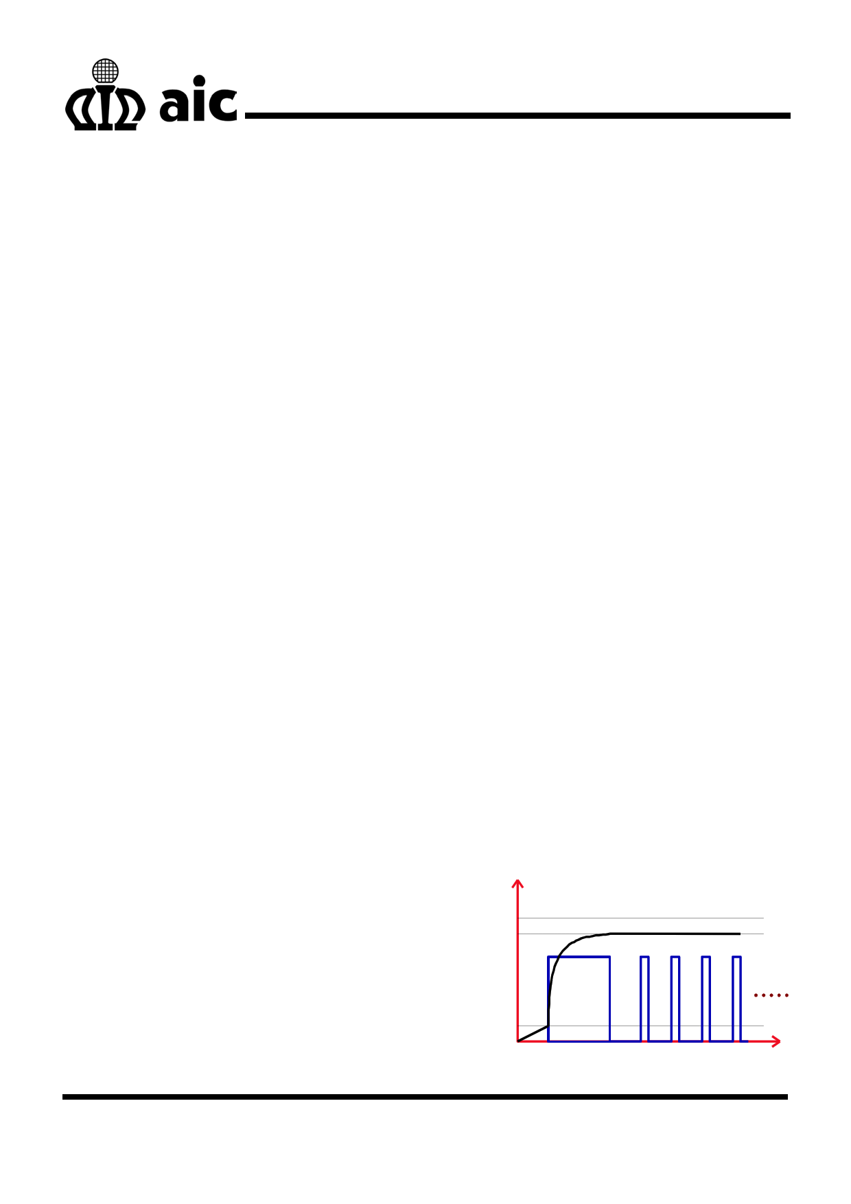
When the battery voltage is lower than the initial
voltage, the charger doesn’t proceed charging due to
estimates the battery hasn’t put in or broken. When
the battery voltage is higher than the initial voltage, the
charger supplies a constant current to battery for fast
charging. When the battery voltage achieves the
saturation voltage, the charger terminates fast
charging. After fast charging, the charger supplies a
trickle current to prevent the loss of battery due to it’s
self-discharging. Fig. 1 illustrates the characteristics of
charger.
Charge Voltage
Maximum
Saturation
Battery Voltage
Trickle Current
Charge
Current
Initial Voltage
Terminate Charge
Time
Fig.1 The charge curve of charger
1
1 page 
AN026
and 47µF/50V.
B. Circuit Structure and Performance
Fig. 9 shows the complete charger circuit. During
charging, there is a voltage from the ICON pin of
AIC1781 to turns the transistor Q3 on. At this while,
RREF2 connect to ground, there is a constant current
from SEPIC and start fast charging. After fast charging,
ICON will deliver a low signal to turns Q3 OFF. At this
while, RREF2 is floating and the voltage between
RREF1 are equal to each other. Then the voltage flows
into FB pin is bigger than the internal reference
voltage 1.22V, and terminate charging. It can support
a discharge route by SW1, and selectable charge
protect functions by SW2~SW5. Fig. 10 is the
recommended layout. Fig. 11 and 12 show the current
and voltage waveforms during SEPIC turns ON and
OFF respectively.
Rlimit
Vin 30m
+ C1
330µF/25V
C2
47nF
1
VIN
2 VREF
3 SHDN
4 FB
CL 8
DHI 7
DLO 6
GND 5
AIC1628
L1
33µH
C4 D1 BAT1
+
47µF
1N5820
REF1
Q1 L2 + 330µF 33K
CEM4410 33µH
N4
C6
REF2
3.3K
GND
BAT1
RA
430K
RB C7 +
68K
4.7µF
R
100K
C8
0.1µF
R5 R6
200 270
LED1
YELLOW
R9
680
C9
47nF
Q2
MPS2222A
R4
Ry
551.1K
Rx1
10.1K
C1
0.1µF
+ C1
R11
200K R13
C11 50K
0.1µF
SW2
SW SPDT
SW1
SW PB
1 PEAK
2 VBT
3 DIS
4 VTS
5 VCC
6 ADJ
7 SEL3
8 TMR
DSW
ICON
LED2
LED1
GND
SEL1
SEL2
MODE
R14
100K
AIC1781
16
15
14
13
12
11
10
9
R12
100K
LED2 LED3
GREEN RED
R15 R16
680 680
U2
78L05
1 VIN VOUT 3
+ C3
GND
1µF 2
+ C5
100uF/10V
Q3
MMBT2222A
Battery N1Battery
GND
N2 GND Battery
GND
SW5
SW SPDT
Fig. 9 The Complete Charger Circuit
SW3
SW SPDT
SW4
SW SPDT
(Top Layer)
(Bottom Layer)
5
5 Page | ||
| Páginas | Total 7 Páginas | |
| PDF Descargar | [ Datasheet AN026.PDF ] | |
Hoja de datos destacado
| Número de pieza | Descripción | Fabricantes |
| AN020 | The Power Management of PDA | AIC |
| AN021 | A Handy Method to Obtain Satisfactory Response of Buck Converter | AIC |
| AN022 | High Side Driver | AIC |
| AN023 | An Useful Model for Charge Pump Converter | AIC |
| Número de pieza | Descripción | Fabricantes |
| SLA6805M | High Voltage 3 phase Motor Driver IC. |
Sanken |
| SDC1742 | 12- and 14-Bit Hybrid Synchro / Resolver-to-Digital Converters. |
Analog Devices |
|
DataSheet.es es una pagina web que funciona como un repositorio de manuales o hoja de datos de muchos de los productos más populares, |
| DataSheet.es | 2020 | Privacy Policy | Contacto | Buscar |