|
|
|
PDF PT7C4339C Data sheet ( Hoja de datos )
| Número de pieza | PT7C4339C | |
| Descripción | Real-time Clock Module | |
| Fabricantes | Pericom Semiconductor | |
| Logotipo | ||
Hay una vista previa y un enlace de descarga de PT7C4339C (archivo pdf) en la parte inferior de esta página. Total 22 Páginas | ||
|
No Preview Available !
PT7C4339/4339C
|||||||||||||||||||||||||||||||||||||||||||||||||||||||||||||||||||||||||||||||||||||||||||||||||||||||||||||||||||||||||||||||||||||||||||||||||||||||||||||||||||||||||||||||||||||||||||||||||||||||||||||||||||||||||||||||||||||||||||||||||||||||||||||||||||||||||||||||||||||||||||||||||||||||||||||||||||||||||||||||||||||||
Real-time Clock Module
Features
Real-Time Clock (RTC) Including Time (Seconds,
Minutes and Hours) and Calendar (Day, Date,
Month and Year with Leap-Year Compensation
Valid Up to 2100) counter functions (BCD code)
Available in a Surface-Mount Package with an
Integrated Crystal (Only for PT7C4339C)
I2C Serial Interface supports I2C-Bus's high speed
mode (400 kHz)
Programmable square wave output signal, defaults
to 32 kHz on Power-up
Two Time-of-Day Alarms
Oscillator Stop Flag
Automatic Power-Fail Detect and Switch Circuitry
Temperature Range: -40°C to +85°C
Package: MSOP-8L and SOIC-8L for PT7C4339
TDFN4x4-8L for PT7C4339C
Applications
Description
The PT7C4339 real-time clock is a low-power
clock/calendar device with two programmable time-of-
day alarms and a programmable square-wave output.
Address and data are transferred serially through an I2C
bus. The clock/calendar provides seconds, minutes,
hours, day, date, month, and year information. The date
at the end of the month is automatically adjusted for
months with fewer than 31 days, including corrections
for leap year. The clock operates in either the 24-hour or
12-hour format with AM/PM indicator. The PT7C4339
has a build-in power-sense circuit that detects power
failures and automatically switch to the backup supply,
maintaining time, date, and alarm operation.
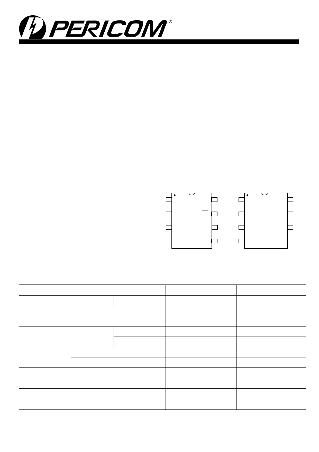
Pin Configuration
PT7C4339
PT7C4339C
1 X1
VCC 8
1 NC
NC 8
2 X2
SQW/INT 7
2 VBACKUP
SCL 7
3 VBACKUP
SCL 6
3 GND
SQW/INT 6
4 GND
SDA 5
4 SDA
VCC 5
SOIC-8
MSOP8
DFN4*4-8L
Table1. Diverse functions of RTC circuits
Item
Function
Source
External crystal
1 Oscillator
Oscillator enable/disable
Oscillator fail detect
2 Time
Time display
Century bit
12-hour
24-hour
Time count chain enable/disable
3 Interrupt
Alarm interrupt output
4 Programmable square wave output (Hz)
5 Communication
2-wire I2C bus
6 Power failure detect
PT7C4339
External crystal
2
1, 4.096k, 8.192k, 32.768k
PT7C4339C
Integrated Crystal
2
1, 4.096k, 8.192k, 32.768k
2015-08-0008
PT0508-1 08/24/15
1
1 page 
PT7C4339/4339C
Real-time Clock Module
|||||||||||||||||||||||||||||||||||||||||||||||||||||||||||||||||||||||||||||||||||||||||||||||||||||||||||||||||||||||||||||||||||||||||||||||||||||||||||||||||||||||||||||||||||||||||||||||||||||||||||||||||||||||||||||||||||||||||||||||||||||||||||||||||||||||||||||||||||||||||||||||||||||||||||||||||||||||||||||||||||||||
Functional Block Diagram
VCC Power Failure Detect
VBACKUP
X1
32.768
kHz
X2
“C” version only
Trickle Charger Control
CD
OSC
CG
Counter Chain
Control Register
SQW/INT
Interrupt Control
Square Wave Output Control
Comparator 1
Comparator 2
Alarm 1 Register
(Sec, Min, Hour, Day/Date)
Alarm 2 Register
(Min, Hour, Day/Date)
Time Counter
(Sec,Min,Hour,Day,Date,Month,Year)
Address
Decoder
Address
Register
Shift Register
I /O
Interface
(I2C)
SCL
SDA
Oscillator Circuit
PT7C4339
The PT7C4339 uses an external 32.768 kHz crystal. Table1 specifies several crystal parameters for the external crystal. The
Block Diagram shows a functional schematic of the oscillator circuit. The startup time is usually less than 1 second when using a
crystal with the specified characteristics.
Table1 Crystal Specifications
Parameter
Symbol
Min
Typ
Max
Unit
Nominal Frequency
fO
-
32.768
-
kHz
Series Resistance
ESR
-
- 70 k
Load Capacitance
CL
-
6
- pF
Note: The crystal, traces, and crystal input pins should be isolated from RF generating signals.
Clock Accuracy
The accuracy of the clock is dependent upon the accuracy of the crystal and the accuracy of the match between the capacitive
load of the oscillator circuit and the capacitive load for which the crystal was trimmed. Crystal frequency drift caused by
temperature shifts creates additional error. External circuit noise coupled into the oscillator circuit can result in the clock running
fast. Figure 2 shows a typical PC board layout for isolating the crystal and oscillator from noise.
PT7C4339C
The PT7C4339C integrates a standard 32,768Hz crystal in the package. Typical accuracy at nominal VCC and +25°C is
approximately ±10ppm.
2015-08-0008
PT0508-1 08/24/15
5
5 Page 
PT7C4339/4339C
Real-time Clock Module
|||||||||||||||||||||||||||||||||||||||||||||||||||||||||||||||||||||||||||||||||||||||||||||||||||||||||||||||||||||||||||||||||||||||||||||||||||||||||||||||||||||||||||||||||||||||||||||||||||||||||||||||||||||||||||||||||||||||||||||||||||||||||||||||||||||||||||||||||||||||||||||||||||||||||||||||||||||||||||||||||||||||
4.3. Time Counter
Time digit display (in BCD code):
Second digits: Range from 00 to 59 and carried to minute digits when incremented from 59 to 00.
Minute digits: Range from 00 to 59 and carried to hour digits when incremented from 59 to 00.
Hour digits: See description on the /12, 24 bit. Carried to day and day-of-the-week digits when incremented from 11 p.m. to
12 a.m. or 23 to 00.
Addr.
Description D7 D6 D5 D4 D3 D2 D1 D0
(hex)
00 Seconds
(default)
0
S40 S20 S10
S8
S4
S2
S1
0 Undefined Undefined Undefined Undefined Undefined Undefined Undefined
01 Minutes
(default)
0
M40 M20 M10
M8
M4 M2
M1
0 Undefined Undefined Undefined Undefined Undefined Undefined Undefined
02 Hours
(default)
0 12, /24 H20 or P,/A H10
H8
H4
H2
H1
0 Undefined Undefined Undefined Undefined Undefined Undefined Undefined
Note: Any registered imaginary time should be replaced with correct time, otherwise it will cause the clock counter malfunction.
12, /24 bit
This bit is used to select between 12-hour clock system and 24-hour clock system.
12, /24
Data
Description
Read / Write
0 24-hour system
1 12-hour system
This bit is used to select between 12-hour clock operation and 24-hour clock operation.
12, /24
Description
Hours register
0 24-hour time display
1 12-hour time display
24-hour clock
00
01
02
03
04
05
06
07
08
09
10
11
12-hour clock
52 ( AM 12 )
41 ( AM 01 )
42 ( AM 02 )
43 ( AM 03 )
44 ( AM 04 )
45 ( AM 05 )
46 ( AM 06 )
47 ( AM 07 )
48 ( AM 08 )
49 ( AM 09 )
50 ( AM 10 )
51 ( AM 11 )
24-hour clock
12
13
14
15
16
17
18
19
20
21
22
23
12-hour clock
72 ( PM 12)
61 ( PM 01 )
62 ( PM 02 )
63 ( PM 03 )
64 ( PM 04 )
65 ( PM 05 )
66 ( PM 06 )
67 ( PM 07 )
68 ( PM 08 )
69 ( PM 09 )
70 ( PM 10 )
71 ( PM 11 )
* Be sure to select between 12-hour and 24-hour clock operation before writing the time data.
4.4. Days of the week Counter
The day counter is a divide-by-7 counter that counts from 01 to 07 and up 07 before starting again from 01. Values that
correspond to the day of week are user defined but must be sequential (i.e., if 1 equals Sunday, then 2 equals Monday, and so on).
Illogical time and date entries result in undefined operation.
Addr.
Description
D7
D6
D5
D4
D3 D2 D1 D0
(hex)
03 Days of the week
0
0
0
(default)
0
0
0
0 0 W4 W2 W1
0 0 Undefined Undefined Undefined
2015-08-0008
PT0508-1 08/24/15
11
11 Page | ||
| Páginas | Total 22 Páginas | |
| PDF Descargar | [ Datasheet PT7C4339C.PDF ] | |
Hoja de datos destacado
| Número de pieza | Descripción | Fabricantes |
| PT7C4339 | Real-time Clock Module | Pericom Semiconductor |
| PT7C43390 | Real-time Clock Module | Pericom Semiconductor |
| PT7C43390C | Real-time Clock Module | Pericom Semiconductor |
| PT7C4339C | Real-time Clock Module | Pericom Semiconductor |
| Número de pieza | Descripción | Fabricantes |
| SLA6805M | High Voltage 3 phase Motor Driver IC. |
Sanken |
| SDC1742 | 12- and 14-Bit Hybrid Synchro / Resolver-to-Digital Converters. |
Analog Devices |
|
DataSheet.es es una pagina web que funciona como un repositorio de manuales o hoja de datos de muchos de los productos más populares, |
| DataSheet.es | 2020 | Privacy Policy | Contacto | Buscar |